Nordson-EFD-725HF-Installation-Guide.pdf
725HF High Flow Series Dispense Valves Installation Guide Electronic pdf files of Nordson EFD manuals are also available at nordsonefd.com Intr oduction The 725HF Series is simple to use and will operate many millions of …
725HF High Flow Series Dispense Valves
Installation Guide
Electronic pdf files of Nordson EFD
manuals are also available at
nordsonefd.com
Introduction
The 725HF Series is simple to use and will operate many millions of cycles
without maintenance.
The unique design of the 725HF Series valve provides a clean fluid cutoff with
pullback for precise fluid application at high cycle rates.
Each 725HF-SS and 725HF-A valve is shipped with a dispensing tip adapter,
fluid inlet fitting and 5-foot actuating air hose installed. For high-flow
applications, the dispensing tip adapter can be removed for installation of
1/4NPT metal or plastic nozzles.
The 725HF-A is identical to the 725HF-SS, except the fluid body and cap are
acetal copolymer, and the shaft and the sealing-head screw are PTFE-coated
stainless steel.
Control air hose
Air cylinder cap
Body cap
Fluid
supply line
Inlet fitting
Air cylinder
Wrench flats
Nozzle
725HF High Flow Series Dispense Valves | Installation Guide
2 www.nordsonefd.com info@nordsonefd.com +1-401-431-7000 Sales and service of Nordson EFD dispensing systems are available worldwide.
Prior to installing this valve, please read the
associated reservoir and valve controller
operating instructions to become familiar
with the operation of all components of the
dispensing system.
Do not thread fluid inlet fittings too far
into the valve. Doing so can obstruct
the piston shaft, causing leakage, poor
dispensing performance, and damage to
the valve.
CAUTION
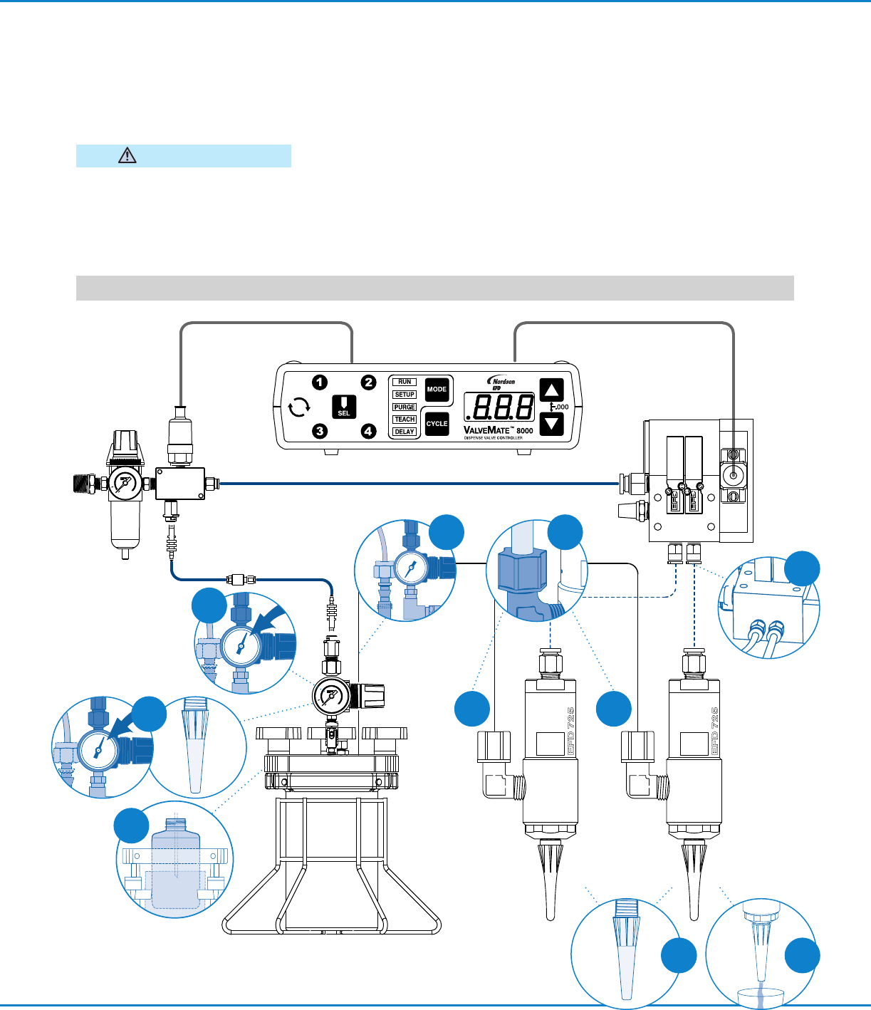
1. Connect the fluid feed hose to the fluid
inlet fitting (#7021038) installed for use
with 3/8" OD tubing and reservoir.
2. Connect the fluid supply line to reservoir.
3. Connect valve control air hose to
ValveMate
™
8000 (solenoid pack) used to
control valve open time.
4. Install nozzle to the valve output.
5. Fill reservoir by pouring fluid directly into
tank liner or manufacturer’s bottle placed
inside reservoir. Secure cover prior to
setting pressure.
6. Set reservoir pressure to low for thin
fluids and higher for thick fluids.
7. Place a cup under the dispensing tip or
nozzle and actuate the valve until fluid
lines, valve and dispensing tip are free
of air.
8. Set desired flow rate by adjusting fluid
reservoir pressure or changing dispensing
tip or nozzle.
Installation
Important Note: Set desired deposit size by adjusting valve open time. Refer to valve controller operating manual.
7
1
1
1
5
6
4
3
2
8
725HF High Flow Series Dispense Valves | Installation Guide
3www.nordsonefd.com info@nordsonefd.com +1-401-431-7000 Sales and service of Nordson EFD dispensing systems are available worldwide.
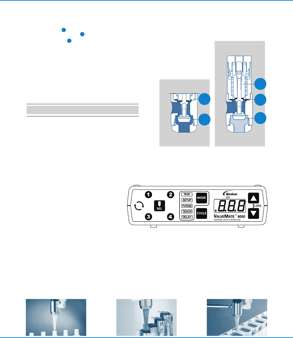
closedopen
How the Valve Operates
Input air pressure at 4.8 bar (70 psi)
*
forces
the internal piston
1
to move down,
causing the diaphragm seal
2
to deflect
and the sealing head
3
to open and permit
fluid flow. When the input air pressure
exhausts, the spring retracts the piston and
the sealing head closes, stopping the fluid
flow and pulling back a slight amount of
fluid.
*
For stripes and lines, input air pressure
can be lowered to eliminate opening
surge.
The primary control of deposit size is the valve open time.
The amount of fluid dispensed will
depend on the time the valve is
open, the viscosity of the fluid, the air
pressure in the fluid reservoir and the
dispensing tip size.
Flow rate is a function of reservoir
pressure, stroke adjustment setting, tip
size and fluid viscosity.
ValveMate Concept
The ValveMate 8000 provides easy adjustment
of valve output for maximum end-user
convenience and efficiency. Valve open time is
the primary control of deposit. The 8000 puts
push-button adjustment of valve open time
where it needs to be—at the valve.
The ValveMate 8000 features micro-processor
circuity for extremely precise control of
deposit size. Feed lines can be purged, initial
deposit sizes set, and adjustments made quickly
and easily at the dispensing station, without stopping the
production line.
Important Note: Order your 1, 2, 3 or 4
solenoid manifold block assembly separately.
Consult EFD for recommendations.
1
2
3
2
3