Nordson-EFD-752HF-Valve-Installation-Guide.pdf
752HF Series High Flow Diaphragm Valves Installation Guide Electronic pdf files of Nordson EFD manuals are also available at nordsonefd.com Intr oduction The 752HF Series fluid dispense valves are simple to use and will op…
752HF Series High Flow Diaphragm Valves
Installation Guide
Electronic pdf files of Nordson EFD
manuals are also available at
nordsonefd.com
Introduction
The 752HF Series fluid dispense valves are simple to use and will
operate many millions of cycles without maintenance. 752HF Series
valves are compact, precise, adjustable diaphragm valves for
dispensing low- to medium-viscosity fluids.
All 752HF Series valves use the same actuating assembly, but fluid
body materials differ depending to the model. The 752HF Series
fluid bodies are constructed with the outlet at the end of the fluid
body. Fluid body materials are:
752HF-SS (#7014315): 303 stainless steel
752HF-A (#7014139): Acetal copolymer
Each valve is shipped with a dispensing tip adapter, fluid inlet fitting,
and 5-foot actuating air hose installed.
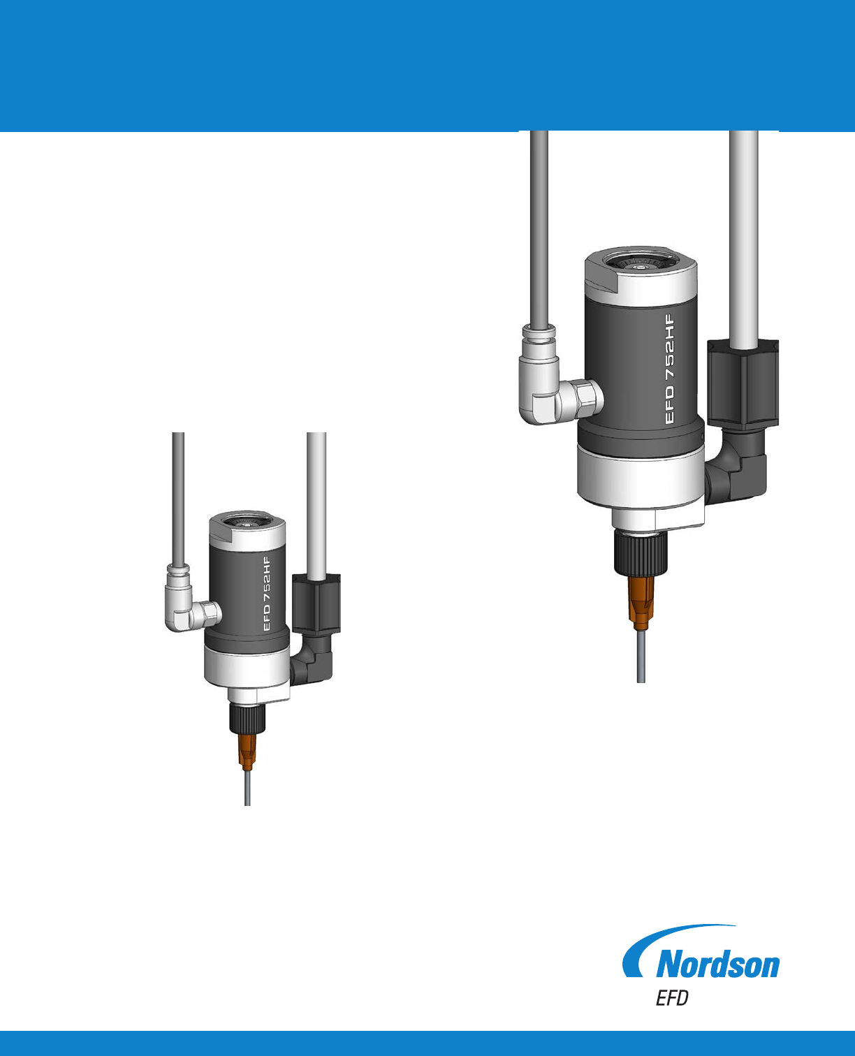
Control air
hose
Fluid body
Fluid
supply line
Inlet fitting
Dispensing tip
752HF Series High Flow Diaphragm Valves | Installation Guide
2 www.nordsonefd.com info@nordsonefd.com +1-401-431-7000 Sales and service of Nordson EFD dispensing systems are available worldwide.
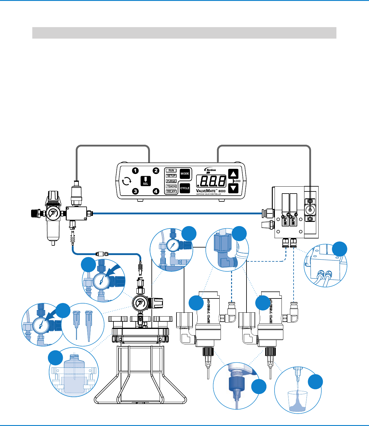
Prior to installing this valve, please read the
associated reservoir and valve controller
operating instructions to become familiar
with the operation of all components of the
dispensing system.
1. Connect fluid supply line to valve. If
3/8" OD tubing is used, change to fitting
#7007038, supplied.
2. Connect the fluid supply line to reservoir.
3. Connect the valve control air hose to the
ValveMate
™
8000 controller (solenoid
pack) used to control valve open time.
4. Press the tip onto the luer slip of the fluid
body. Install the tip retaining nut. Finger-
tighten only. Do not over-tighten as this
may cause damage / cracking of the tip
hub.
5. Fill the reservoir by pouring fluid directly
into the tank liner, or the manufacturer’s
bottle placed inside the reservoir. Secure
the cover prior to setting the pressure.
6. Set the reservoir pressure to low for thin
fluids and higher for thick fluids.
7. Set the diaphragm stroke starting at no
more than 1/2 turn open.
*
8. Place a cup under the dispensing tip
and actuate the valve until the fluid lines,
valve, and dispensing tip are free of air.
9. Set the desired flow rate by adjusting the
fluid reservoir pressure or changing the
dispensing tip.
*
Do not overtighten the stroke adjustment
knob or open it more than two full turns.
If it is opened more than two turns,
pressurized liquid could force open the
diaphragm seal, resulting in continuous
liquid flow.
Installation
8
1
1
5
4
3
2 1
6
9
Important Note: Set desired deposit size by adjusting valve open time. Refer to valve controller operating manual.
752HF Series High Flow Diaphragm Valves | Installation Guide
3www.nordsonefd.com info@nordsonefd.com +1-401-431-7000 Sales and service of Nordson EFD dispensing systems are available worldwide.
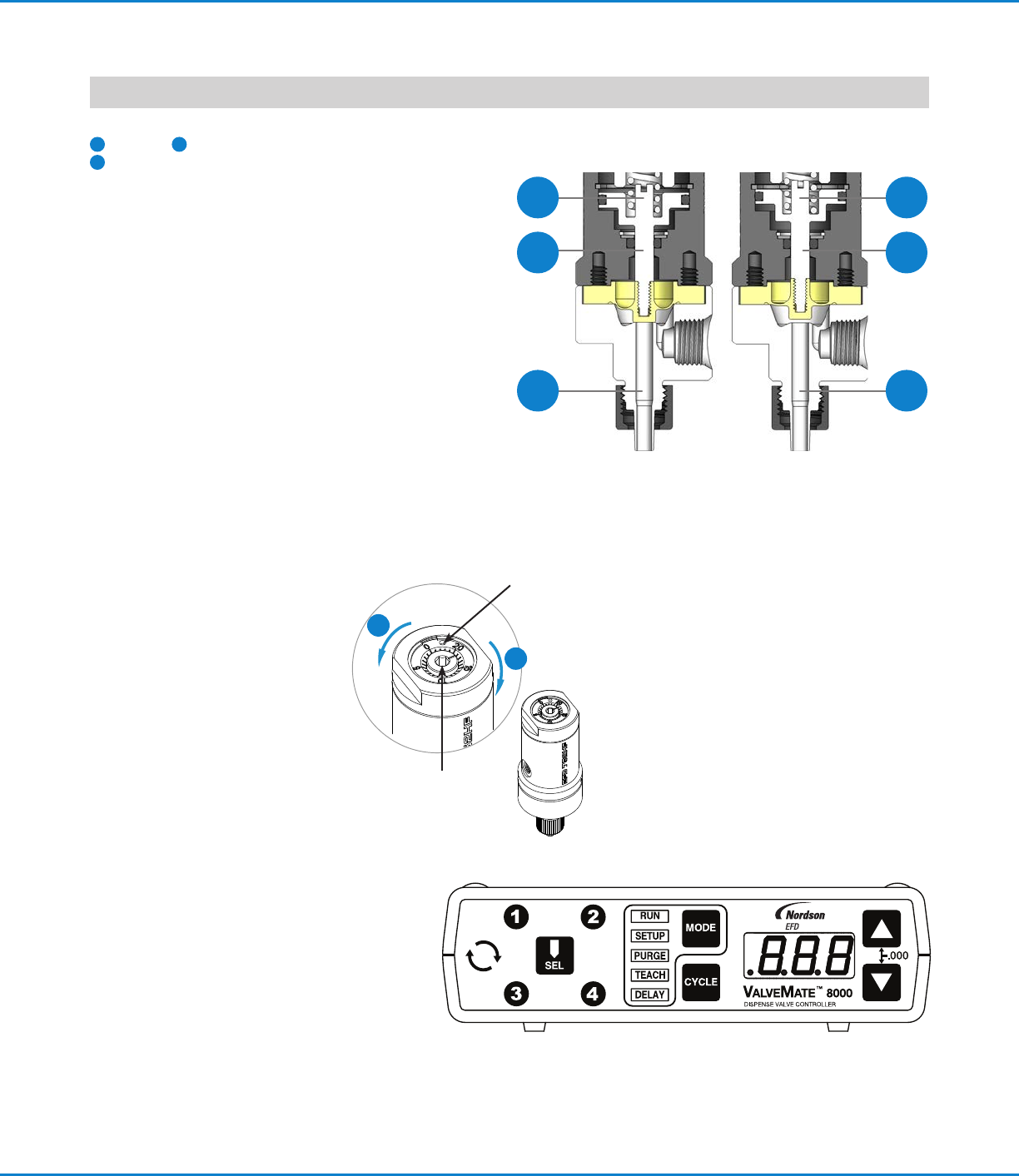
How the Valve Operates
Input air pressure at 4.8 bar (70 psi) forces the internal piston
1
to move.
2
The piston rod pulls open the diaphragm seal,
3
permitting fluid flow. When the input air pressure is
relieved, the spring retracts the piston and the diaphragm
closes.
The amount of fluid dispensed depends on the time the valve
is open, the viscosity of the fluid, the air pressure in the fluid
reservoir, the dispensing tip size, and the diaphragm stroke.
Flow rate is a function of reservoir pressure, tip size, and
fluid viscosity.
To calibrate the valve:
a. Insert a 3 mm hex wrench into the stroke control port.
b. Turn the inner knob clockwise until there is a full stop
against the internal actuator piston.
c. Insert a 1.5 mm hex wrench into the stroke control ring
hole.
d. Apply slight pressure and rotate until the 0 aligns with the
stroke control port hash mark.
e. The stroke control is now
calibrated. Insert a 3 mm hex
wrench into the stroke control
port and turn counterclockwise to
secure the stroke flow control.
ValveMate Concept
The ValveMate 8000 provides easy adjustment
of valve output for maximum end-user
convenience and efficiency. Valve open time is
the primary control of deposit. The 8000 puts
push-button adjustment of valve open time
where it needs to be—at the valve.
The ValveMate 8000 features micro-processor
circuity for extremely precise control of deposit
size. Feed lines can be purged, initial deposit
sizes set, and adjustments made quickly and easily at
the dispensing station, without stopping the production line.
Important Note: Order your 1, 2, 3 or 4
solenoid manifold block assembly separately.
Consult EFD for recommendations.
openclosed
1
2
3
1
2
3
e
b
Control ring hole
Stroke control
port
The primary control of deposit size is the valve open time.
752HF-SS and 752HF-A Fluid Flow