Hanwha DECAN Series.pdf
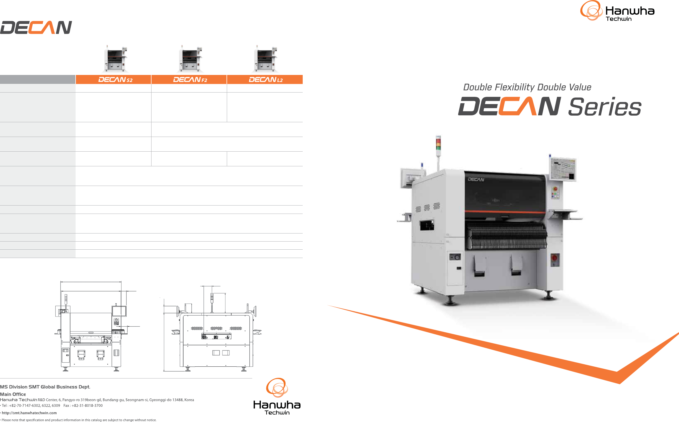
1,430 1,430 135 155 195 181 510 247 1,485 (Conv eyor to Conv eyor) (Cover t o Cover) (Monitor) (Keyboard) ( T ow er Lamp) (Monitor) ( T ow er Lamp) (F/R Lamp) (Cower T op) S e r i e s Double Flexibili ty Double V alue Di…
1,430
1,430 135
155
195
181
510
247
1,485
(Conveyor to Conveyor)
(Cover to Cover) (Monitor)
(Keyboard)
(Tower Lamp)
(Monitor)
(Tower Lamp)
(F/R Lamp)
(Cower Top)
Series
Double Flexibility Double Value
Dimension
Experience Your SMART FACTORY
*
Under optimum condition of specified by HANWHA TECHWIN.
Model
# of Spindles 2 Gantry x 10 Spidles/Head 2 Gantry x 10 Spidles/Head 2 Gantry x 6 Spidles/Head
Placement Speed
(Under optimum condition of
as defined by Hanwha Techwin.)
92,000 CPH (Optimum) 80,000 CPH (Optimum)
56,000CPH (Flying Vision, Optimum)
-
0.14 seconds/component
(Flying Vision, SOIC 0.5P)
-
0.55 seconds/component
(Upward Vision, QFP100 0.5P)
Vision Flying Vision
Flying Vision
Stage Vision(Option)
Placement Accuracy
±28µm Cpk≥1.0 (03015 chip)
±25µm Cpk≥1.0 (IC)
±40µm Cpk≥1.0 (0402 (01005 inch) chip)
±30µm Cpk≥1.0 (IC, Stage Vision)
Component Range 03015 ~
□
12mm (H10mm)
0402 (01005) ~
□
16mm (H10mm)
Max.
□
42mm (H15mm) (Option)
0402 (01005) ~
□
21mm (H12mm)
Max.
□
55mm (H25mm) (Option)
PCB Size
50 x 40 ~ 510 x 460mm (Standard)
~ 610 x 460mm (Option), ~ 740 x 460mm (Option)
~ 810 x 460mm (Option), ~ 1,200 x 460mm (Option)
Conveyor Configurations
Standard : 1-2-1
Option : 1-2-2/2-2-2/2-2-1/1-1-1
Factory Option : Single Conveyor (Jedec Tray 2ea)
Feeder Capacity 120ea (8mm)
Power
Voltage : 3 phase AC200/208/220/240/380/415V ±10%
Frequency : 50/60Hz
Power Consumption : Max. 5.0kVA
Air Consumption 50Nl/min
Weight About 1,800kg
External Dimensions (mm) 1,430(L) x 1,740(D) x 1,485(H)
Specications
Experience Your SMART FACTORY
Wide Part Handling Capability
•
Part capability of 03015 ~
ㅁ
55mm (H25mm)
•
Performs placement by recognizing the characteristics of the LED
and Lens
Full Dual Conveyor
Shuttle Dual Conveyor
Various PCB Transfer Systems
•
Various structures maximizing productivity
•
1,200mm long PCBs
•
Long boards (1,200 x 460mm)
•
Dual lane as standard
Verified Production History Management Solution
•
Parts verification (Prevents misplacement)
•
Traceability (Lot tracking)
•
T-LTS : Lot tracking for traceability
C160 8-5 60pF
C160 85 60PF9907141301
C160 8-5 60pF
C160 85 60PF9907141301
High Speed Placement
•
Minimizes the placement cycle time by recognizing the picked
part and correcting the placement angle while moving to the
placement position after picking the part
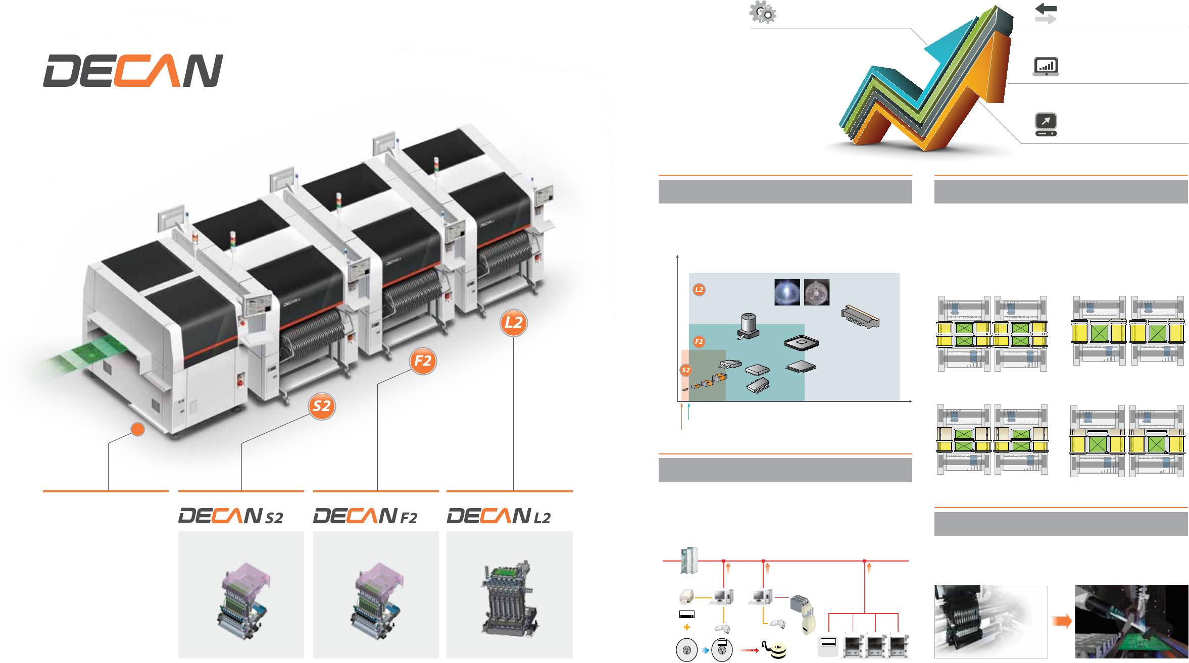
Series
Double Flexibility
Double Value
Advanced Multi- Functional PlacerAdvanced Chip Shooter Advanced Flexible Placer
Screen Printer
•
56,000 CPH
•
0402 ~
□
55mm (H25mm)
•
92,000 CPH
•
03015 ~
□
12mm (H10mm)
•
80,000 CPH
•
0402 ~
□
42mm (H15mm)
FS06 HeadFS10 HeadFS10 Head
EtherNet (TCP/IP)
Barcode
Printer
Reel Barcode
Reader
Reel Barcode Reader
SM Feeder
1D/2D
DeviceNet
Height
(mm)
Width
(mm)
25
15
10
ㅁ
12
ㅁ
42
ㅁ
55
ㅁ
75
03015
0402 (01005 inch)
High Speed Placement
Verified Production History
Management Solution
Various PCB Transfer Systems
Wide Part Handling Capability
FLEXIBILITY PRODUCTIVITY RELIABILITY EASY OPERATION
Why DECAN?
Modular conveyor system for various production
environments
•
Allows optimum conveyor module combination according to a
production line by applying a modular conveyor that can be replaced
on site (Shuttle ↔ Dual)
Dual lane PCB transfer system for the improvement
of productivity
•
Zero PCB loading/unloading time by loading the PCB on the opposite
lane and having it stand by during operation (Productivity increases
by 15% compared to a single lane machine)
Increased convenience of machine software operation
•
The built-in optimization software allows a PCB program to be easily
created and edited
•
Provides various PCB information through a large LCD screen
Reduces the cycle time by sharing bad marks with
other machines
•
Shares the information of the bad mark of the PCB recognized by the
first machine with other machines in the line
•
Reduces the placement cycle time since the bad mark inspection is
omitted by sharing the bad mark information
Utilising linear motors reducing noise and vibration
•
Applies the twin servo control and linear motor to the Y-axis to realize
low noise and vibration
Allows mixed use of an electrically driven feeders
and pneumatic feeders
•
Allows mixed use of electrically driven feeders and
pneumatic feeders in the same feeder base
•
Allows the electrically driven feeders and
pneumatic feeders to be used together
with existing feeders, which helps
reduce production costs
Machine applicable to large PCBs that can be modified
on site
•
The standard machine can be modified on site to handle large PCBs
- Applicable to Max. 1,200 x 460mm PCBs
•
Possible to produce 1,200mm long boards on dual lane
•
Wide part handling capability and flexible conveyor optionssuitable for various PCBs
•
Reduces production time
by optimizing the motion sequence and sharing the data with other machines
•
Reinforces odd-type part recognition
by applying a 3D lighting system and improving the vision algorithm
•
High reliability of machine operation and increased convenience of operation
by listening to customers' requirements
1-2-2 2-2-2 2-2-1
Work PCB
Standby PCB
Standard 1
st
Machine
Medium
Machine
Last
Machine
Extra Large
PCB
In-let 1 (Shuttle) 1 (Shuttle) 2 2 1
Work 2 2 2 2 1
Out-let 1 (Shuttle) 2 2 1 (Shuttle) 1
Congurations
Places high precision Can Connector parts and
LED/LED lenses
Electrically Driven Feeder
Maximizes productivity by increasing simultaneous
pickup rate
•
Increases the simultaneous pickup rate by automatically correcting
pickup positions
Side
Outer
Coaxial
Part
Normal
180°
Rotation
Flip-over
LED Micro BGA
Before
improvement
Before
improvement
After
improvement
After
improvement
Optimizes the placement of LED lenses
•
LED direction and recognition
of different types of LEDs
•
Minimizes defective placement
by recognizing the protruded
positions
•
Places a lens based on the
light source by recognizing
the LED light source
Patent Registration
No. 1472444
Automatic tape connection reduces the work volume
by half (Smart Feeder)
• Utilising
the automatic tape loading and splicing for the first time in the
SMT industry - Minimizes the part reel replacement time by automating
the tape loading and splicing that was previously performed manually
•
Zero cost for consumables for tape splicing
Connecting Reel
Reel in use
Automation
Experience Your SMART FACTORY
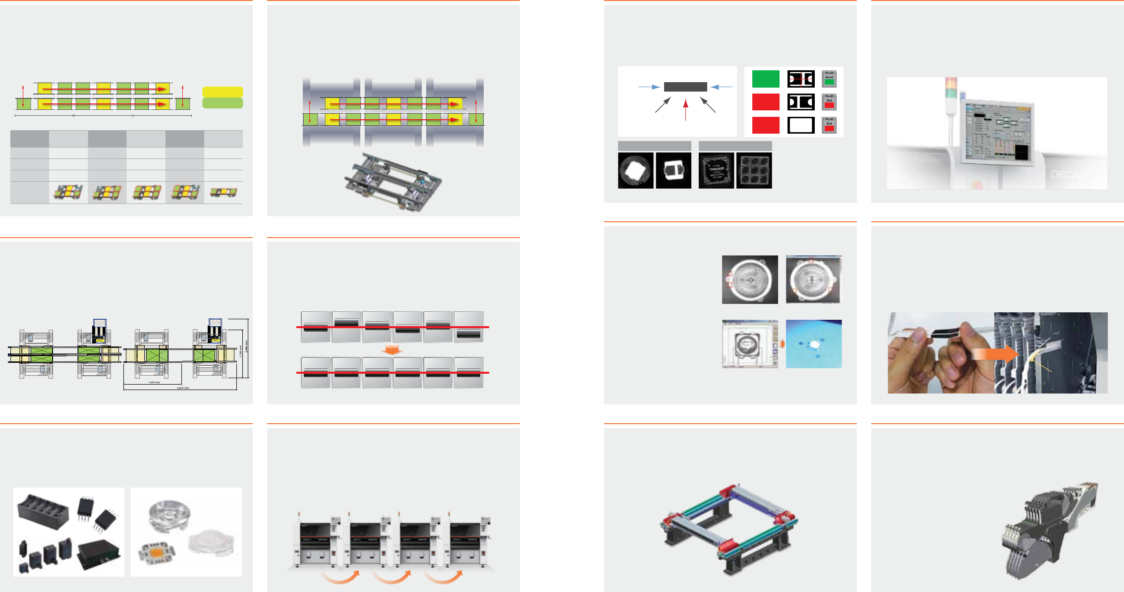
Prevents reverse placement by recognizing the polarity
mark at the bottom surface of a part
•
Recognizes the polarity mark on the bottom surface of a part using the
3-stepped 3D lighting
Existing Recognition
Method
Special Lighting
Irradiation