吸嘴交换站ANCsensorAdjustStep.pdf
Service Engineer Service Informati on No: SI120 5003E - 000 = ANC con trol board n ozzle sensor adjustmen t procedure 1/ 12 MACHINE T YPE : YS12 (YG12) series, YS24(X) series, YS100, YS88 , YG300 CLASSIFICATION : Adjustm…
Service Engineer
Service Information
No: SI1205003E-000= ANC control board nozzle sensor adjustment procedure
1/12
MACHINE TYPE : YS12 (YG12) series, YS24(X) series, YS100,
YS88, YG300
CLASSIFICATION : Adjustment / Troubleshooting
REFERENCE : H016942
ANC control board nozzle sensor adjustment procedure
General description
This document describes how to check and perform adjustment for when the nozzle detection sensor
of the ANC (Nozzle station) with the “ANC control board Assy.” is unstable.
About this document:
・ Make sure to use it under the instruction of those who have completed the maintenance training or a
YAMAHA serviceman.
・ YAMAHA is not responsible for any problems caused by the misuse of the document.
・ This document contains the method to edit the system data that affects the customer’s machine
condition.
・ Make sure to thoroughly understand the contents of the document, and perform the adjustments on
your own responsibility.
About the safety:
Strictly follow the safety precautions in the “Safety” section in the “Operation Manual”.
Disclaimers:
This document contains the preliminary information subject to change in the future.
The information contained in this document represents the current view of YAMAHA on the issues
discussed as of the date of issuance. As YAMAHA must respond to changing market conditions, it should
not be interpreted to be a commitment on the part of YAMAHA, and YAMAHA cannot guarantee the
accuracy of any information presented after the date of issuance.
This document is provided for information purposes only, and it is provided without any warranties, either
express or implied.
It is the responsibility of the user to comply with all applicable copyright laws. Without limiting the rights
under copyright, no part of this document may be reproduced, stored in or introduced into a retrieval system,
or transmitted in any form or by any means (electronic, mechanical, photocopying, recording, or otherwise),
or for any purpose, without the written permission of YAMAHA.
However, this shall not be construed to limit the user’s right granted by Copyright law.
YAMAHA may have patents, patent applications, trademarks, copyrights, or other intellectual property rights
covering subject matter in this document. Except as expressly provided in any written license agreement
from YAMAHA, this document does not give users any license to these patents, trademarks, copyrights, or
other intellectual property.
The names of actual companies and products mentioned in this document may contain the trademarks of
their respective owners.
Table of contents
1. Check if the sensor detects the nozzle properly ............................................................................ 2
1.1 Operation check of the sensor on the I/O window .................................................................................. 2
1.2 Check the threshold of the sensor by the CalibSm ................................................................................. 4
1.2.1 Start up CalibSm adjustment utility .................................................................................................................. 4
1.2.2 When “Nozzle change” can be performed ....................................................................................................... 5
1.2.3 When “Nozzle Change” cannot be performed automatically ............................................................................ 7
2. Clean the parts of the ANC related to nozzle detection ................................................................ 9
2.1 Clean the Acrylic board ........................................................................................................................... 9
2.2 Clean the light path of the sensor ......................................................................................................... 10
2.3 Adjust the sensor threshold .................................................................................................................. 10
3. Countermeasure for the LED light leak from the ANC control board area ................................ 11
4. Replace the ANC control board ..................................................................................................... 12
No: SI1205003E-000
ISSUED DATE: December 24, 2012
Service Engineer
Service Information
No: SI1205003E-000= ANC control board nozzle sensor adjustment procedure
2/12
1. Check if the sensor detects the nozzle properly
1.1 Operation check of the sensor on the I/O window
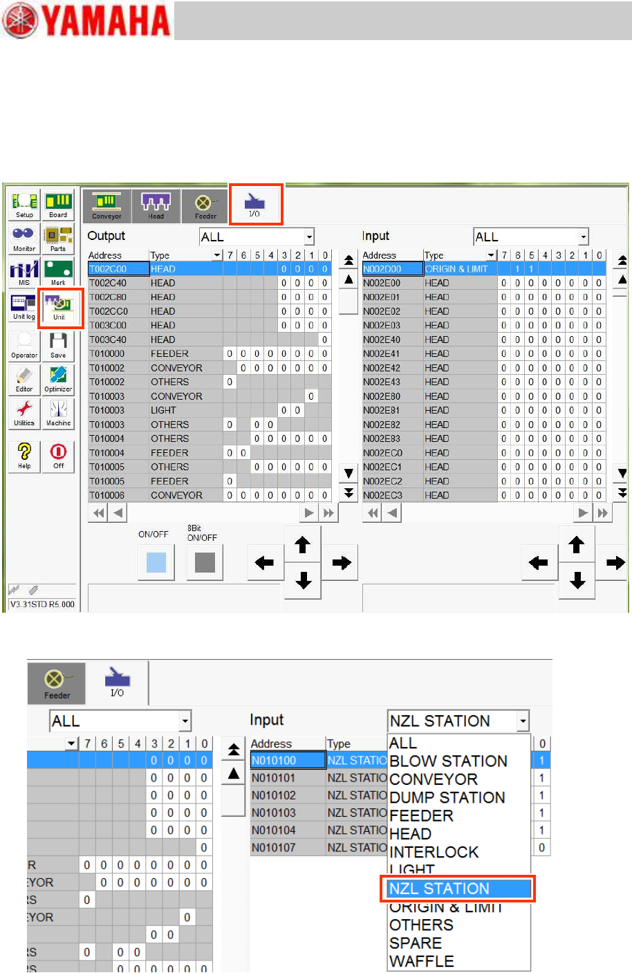
1. Display the I/O window.
Click the [Unit] button and select the “I/O” tab.
Figure 1
2. Select “NZL STATION” from the “Input” pull-down menu.
Figure 2
Service Engineer
Service Information
No: SI1205003E-000= ANC control board nozzle sensor adjustment procedure
3/12
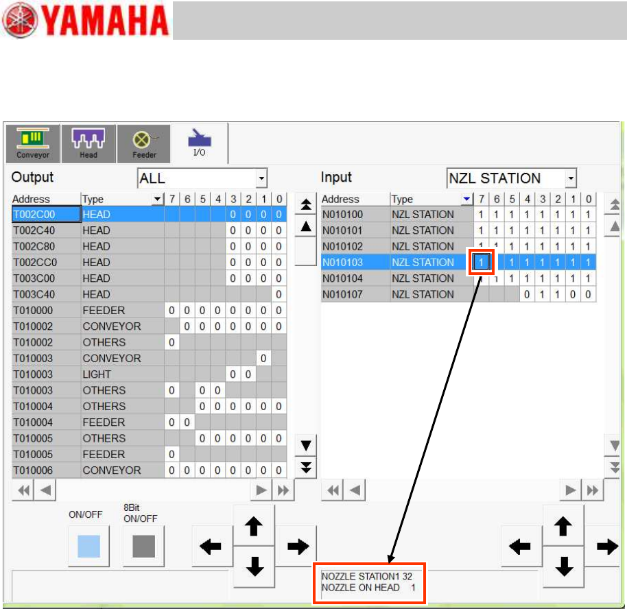
3. Select the nozzle number of the nozzle station to be checked.
The nozzle number and the condition of the sensor are displayed at the lower part of the window.
Check if the indication of “0/1” switches properly by taking a nozzle in and out the nozzle station.
Figure 3