NOZZLE-EN_-ZEVAC-Flyer.pdf
GAS NO ZZLES FOR SM T COMPONEN T S The distribution of this document is not permitted without express permission – 02.22
GAS NOZZLES FOR
SMT COMPONENTS
The distribution of this document is not permitted without express permission – 02.22
Swiss Engineering
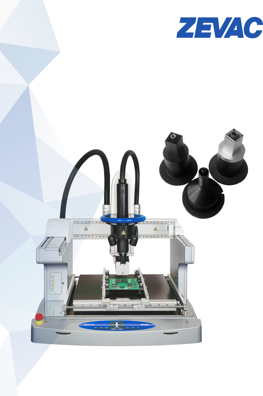
GAS NOZZLE DEFINITION
For quotations and orders the advice for the system type (DRS or ONYX) is required and the following dimensions are necessary
for the denition of the gas nozzle:
EZ / EZL GAS NOZZLES
For PBGA, TBGA, CBGA, CCGA SBGA
EZ gas nozzle / EZL gas nozzle
• Distance to the next component: 0.0 mm
• Vacuum tube is adjustable
Order No. Component dimensionen in mm
W1 W2 W3 W4 H1
CH N 394 EZ(L) 394 10.0 10.0
CH N 700 EZ(L) 700 18.0 18.0
CH N 826 EZ(L) 826 21.0 21.0
CH N 984 EZ(L) 984 25.0 25.0
CH N 1062 EZ(L) 1062 27.0 27.0
CH N 1220 EZ(L) 1220 31.0 31.0
CH N 1377 EZ(L) 1377 35.0 35.0
CH N 1574 EZ(L) 1574 40.0 40.0
CH N 1732 EZ(L) 1732 44.0 44.0
Examples
GAS NOZZLES – FOR SMT COMPONENTS
Swiss Engineering
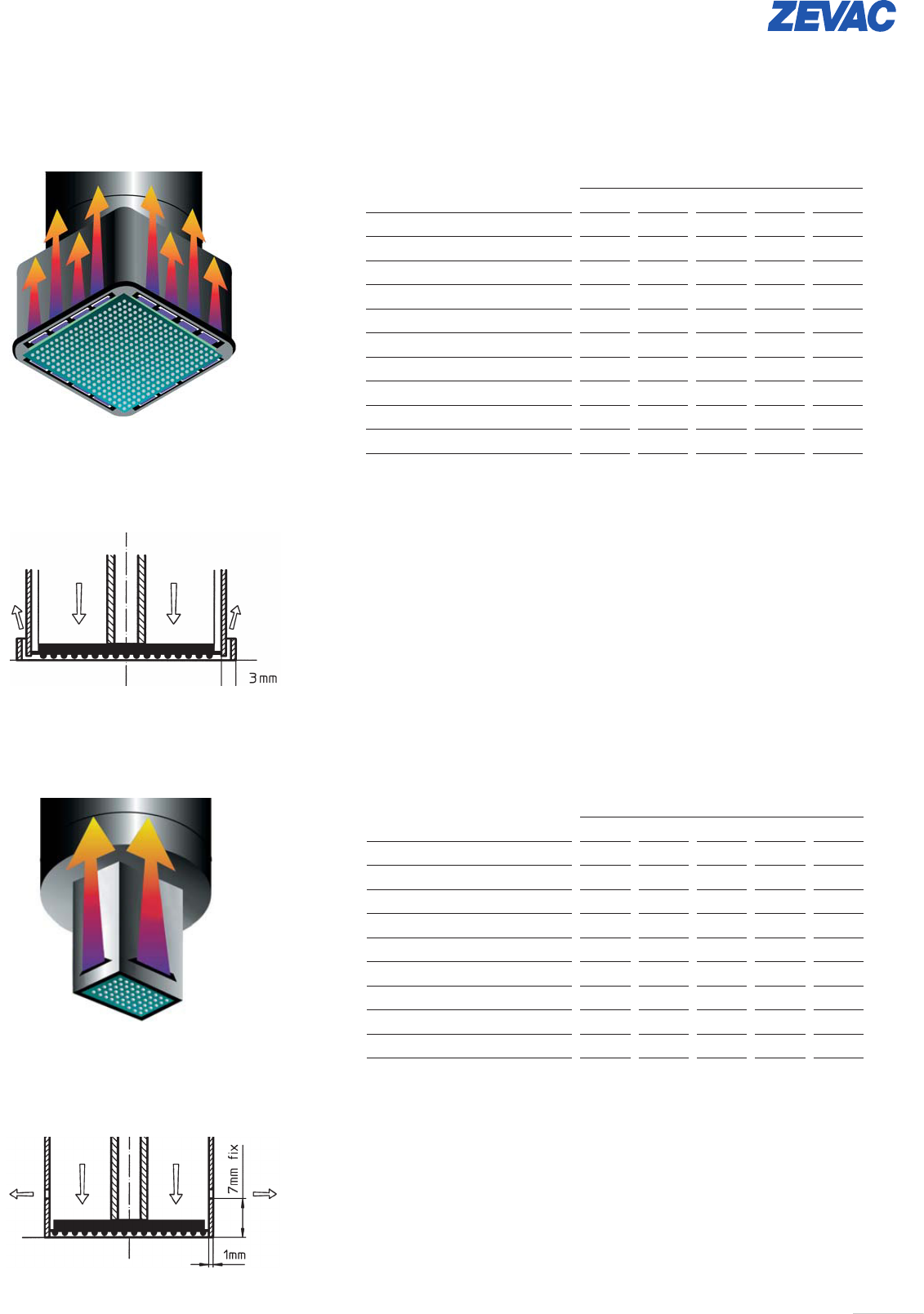
Y GAS NOZZLES
For PBGA, TBGA, CBGA, CCGA SBGA
Y Gas Nozzle
• Distance to the next component: min. 1.0 mm
• The vacuum tube is adjustable
Order No. Component dimension in mm
W1 W2 W3 W4 H1
CH N 488 Y 488 12.1 12.1 7
CH N 1235 Y 1235 31.1 31.1 7
CH N 1244 Y 1244 31.3 31.3 7
CH N 1345 Y 1345 33.9 33.9 7
CH N 1393 Y 1393 35.1 35.1 7
CH N 1483 Y 1483 37.4 37.4 7
CH N 1582 Y 1582 39.9 39.9 7
CH N 1590 Y 1590 40.1 40.1 7
CH N 1688 Y 1688 42.6 42.6 7
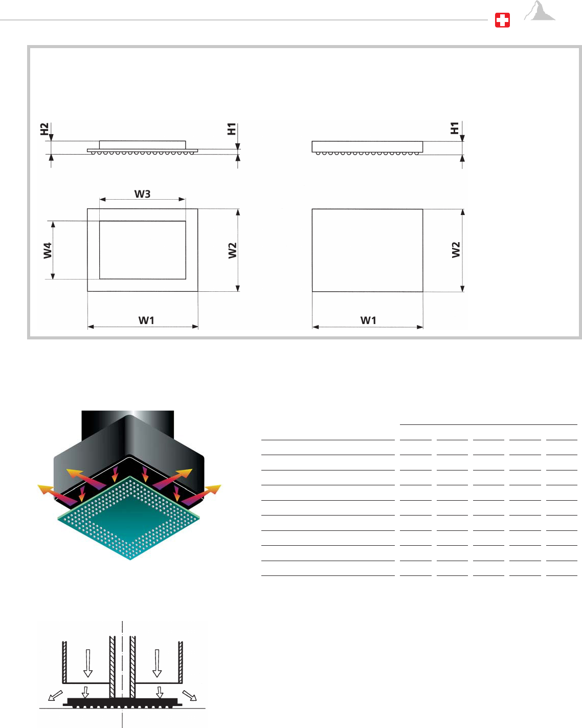
X GAS NOZZLES
For PBGA, TBGA, CBGA, CCGA SBGA
X Gas Nozzle
• Distance to the next component: min. 3.0 mm
• Vacuum tube is adjustable
Order No. Component dimensions in mm
W1 W2 W3 W4 H1
CH N 400 X 400-11 9.9 9.9 0.7
CH N 562 X 881-17 14.0 22.1 1.3
CH N 687 X 687-15 17.2 17.2 1.1
CH N 842 X 842-20 21.1 21.1 1.6
CH N 921 X 921-22 23.1 23.1 1.8
CH N 1081 X 1081-15 27.2 27.2 1.1
CH N 1232 X 1232-17 31.0 31.0 1.3
CH N 1433 X 1433-17 36.1 36.1 1.3
CH N 1594 X 1594-18 40.2 40.2 1.4
CH N 1606 X 1606-22 40.5 40.5 1.8
Examples
Examples