vm_series_brochure.pdf
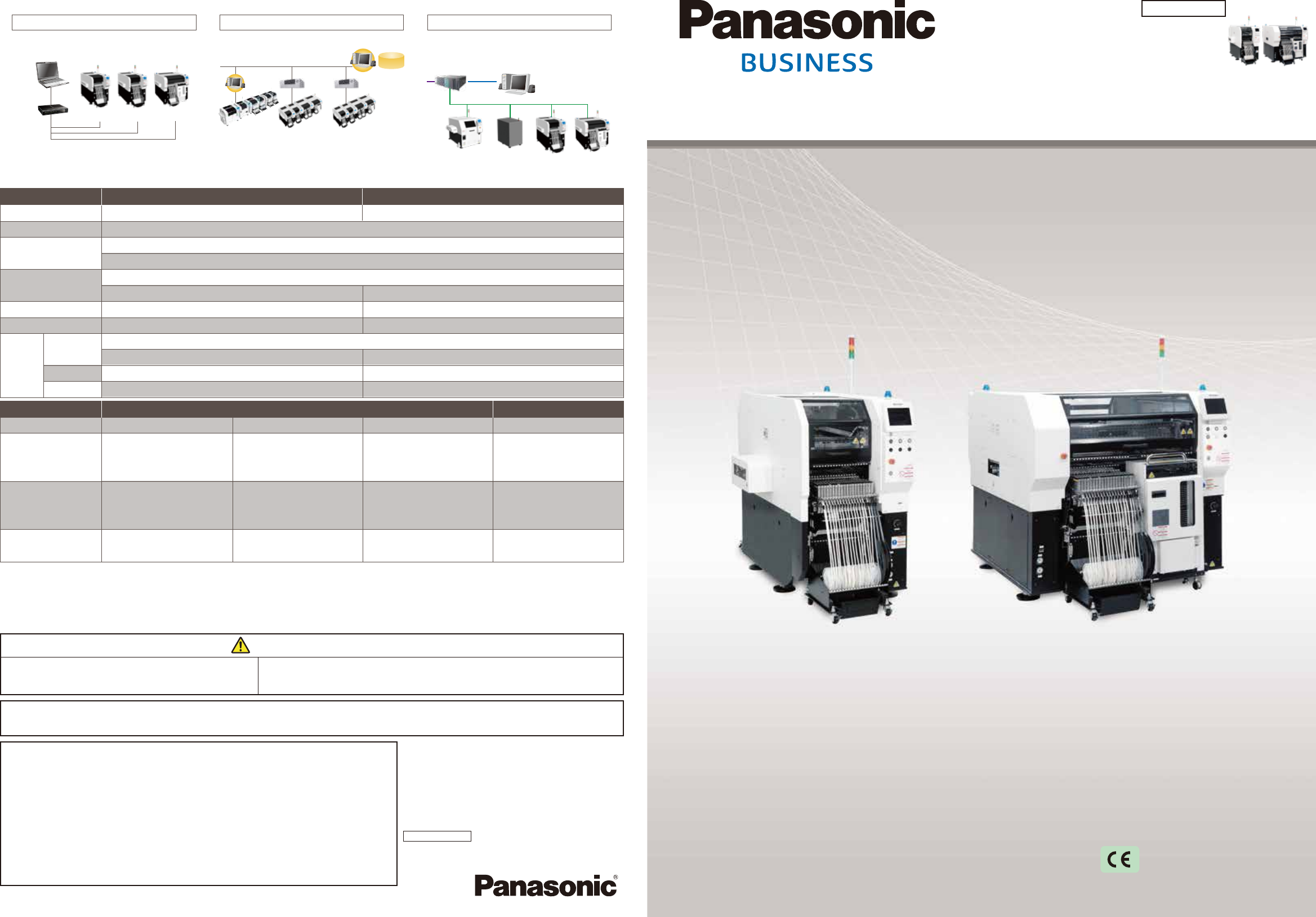
2020 Modular Placement Machine Electronics Assembly System catalog Modular Placement Machine VM series Model Name Model Name VM 1 0 1 VM 1 0 2 Model No. NM-EJM3E Model No. NM-EJM4E *It may not conform to Machinery Direct…
2020
Modular Placement Machine
Electronics Assembly System
catalog
Modular Placement Machine
VM series
Model Name Model Name
VM101 VM102
Model No.
NM-EJM3E
Model No.
NM-EJM4E
*It may not conform to Machinery Directive
and EMC Directive in case of optional
configuration and custom-made specification.
System configuration (minimum)
For three machines or less, minimum system
configuration is available, with both AM-LNB and
NPM-DGS on a single PC.
♯3
VM102
♯2
VM101VM101
PC
HUB
♯1
*1 : Prepare a PC for AM-LNB on your own.
*2 : Depending on the option you select, you may need an FA PC for LNB.
*1
*2
(AM-LNB
&
NPM-DGS)
Integrated line management (iLNB)
VM101 VM102
iLNB
NPM-DGS
Data creation (NPM-DGS)
Software package to crate, edit or simulate
production data, or integratedly manage the library.
NPM-DGS
PT200
FA PC
(LNB)
FA PC
(LNB)
*1 : A PC must be purchased separately.
*2:NPM-DGS has two functions; the floor level control and line level control.
*3:LNB(Line Network Box)
Line is created with several machines to centralize and control information.
*4:For connection with NPM series in VM line, contact your local sales representative.
*1
*1、2
*3 *3
*4 *4
Library
database
CM line
VM line VM line
Inspection
machine
Screen printer
Connecting via a PC to other vendorsʼ machines
allows for collective line control over changeover,
operation performance, quality control or process
support, etc.
VM101 VM102
NM-EJM3E NM-EJM4E
100 L /min(A.N.R.) 200 L /min(A.N.R.)
W 830
mm
× D 1 969
mm
× H 1 500
mm
W 1 515
mm
× D 2 070
mm
× H 1 500
mm
W 1 515
mm
× D 2 070
mm
× H 1 500
mm
Max.20
Max.160 components (4/8
mm
tape)
Max.20
Max.40
Max.20
Max. 80 components (4/8
mm
tape)
Model ID
PCB dimensions
Electric sourceElectric source
Pneumatic sourcePneumatic source
DimensionsDimensions
Model No.
*1
Mass
Taping
Stick
Tray
Component
supply
L 50
mm
× W 50
mm
∼ L 330
mm
× W 250
mm
L 50
mm
× W 50
mm
∼ L 330
mm
× W 250
mm
(Single-lane)(Single-lane)
0.5 ∼ 0.8 MPa
1.3 kVA
3-phase AC 200, 220, 380, 400, 420, 480 V
*2*2 *3*3
*5*5 *5*5
*4*4 *4*4
*3*3
1 500 kg1 500 kg
(Front: Fixed supply unit, Rear: Fixed supply unit without cutting unit)(Front: Fixed supply unit, Rear: Fixed supply unit without cutting unit)
1 910 kg1 910 kg
(Front: Fixed supply unit plus tray, Rear: Fixed supply unit without cutting unit)(Front: Fixed supply unit plus tray, Rear: Fixed supply unit without cutting unit)
Tape:4 ∼ 56 / 72 / 88 / 104
mm
VM101 VM102
42 000 cph
(0.086 s / chip)
22 500 cph
(0.160 s / chip)
8 200 cph
(0.439 s / chip)
6 500 cph
(0.554 s / QFP)
32 100 cph
(0.112 s / chip)
10 500 cph
(0.343 s / QFP)
±30 μm / chip ±30 μm / QFP
±30 μm /
chip
±50 μm / QFP
□
12
mm
Under
±30 μm / QFP
□
12
mm
∼
±40 μm /
chip
±50 μm / QFP
□
12
mm
Under
±30 μm / QFP
□
12
mm
∼
0402
chip
∼ L 6 × W 6 × T 3
0402
chip
∼ L 45 × W 45 × T 12
or L 100 × W 40 × T 12
0603
chip
∼ L 120 × W 90 × T 30
or L 150 × W 25 × T 30
0402
chip
∼ L 120 × W 90 × T 28
or L 150 × W 25 × T 28
*6*6
*7*7
Model ID
Placement head
(
mm
)
Max. speed
Component dimensions
Placement accuracy(Cpk≧1)
Lightweight 16-nozzle head V2 Lightweight 8-nozzle head
4-nozzle head 14-nozzle head
* Placement tact time and accuracy values may
differ slightly depending on conditions.
*Please refer to the specification booklet for details.
*1: The machine dimensions differ depending on specifications.
*2: For the safety of transport openings, you need to select extension
conveyor specifications for any VM101 located at the far right/left of a line.
*3: The dimensions of VM101 with the fixed supply unit selected for its front
and rear sides are the same as the ones of VM102 with the tray feeder
and the fixed supply unit selected for its front and rear sides, respectively.
The reel holder and reel box are not included in the dimensions.
*5: The number of stick model types available for the machine
equipped with the single stick feeder.
*4: When the double feeder is used as tape feeder.
*6: Under our optimal conditions
*7: Support for 0402 placement is optional.
3-1-1 Inazu-cho, Toyonaka City, Osaka 561- 0854, Japan
TEL +81-6-6866-8675
FAX +81-6-6862-0422
Inquiries…
Safety Cautions
●Please read the User's Manual carefully to
familiarize yourself with safe and effective
usage procedures.
● To ensure safety when using this equipment, all work should be
performed according to that as stated in the supplied Operating
Instructions. Read your operating instruction manual thoroughly.
Panasonic Group products are built with the environment in mind.
●Changes in specifications and appearance may be made without notice for product improvement.
●Homepage
Panasonic Corporation
Process Automation Business Division
Ver.January 1, 2020
All data as of January 1, 2020
©
Panasonic Corporation 2020
panasonic.com/global/corporate/sustainability
Please check the homepage for the details.
industrial.panasonic.com/ww/fa-jisso
Rotary Head Mounter Line
(HT122+BM221)
VM101 VM102
32 100 cph
Max. speed
*
2 470
1 900
9 060
2 372
3 365
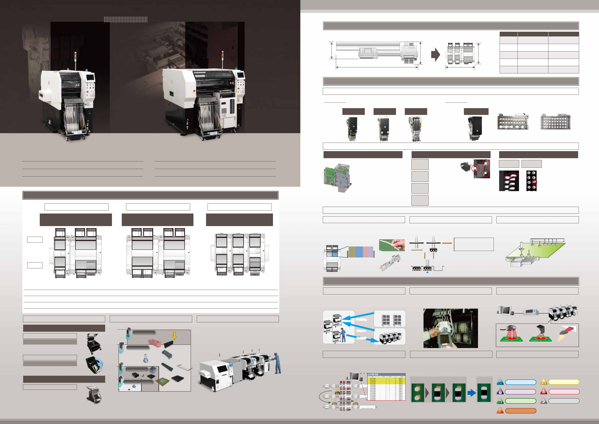
Rotary Head Mounter Line
84 545 cph 93 500 cph
W 9 060 ㎜ × D 2 470 ㎜
× H 1 800 ㎜
W 3 365 ㎜ × D 2 372 ㎜
× H 1 500 ㎜
0402 ~ 120 × 90
㎜
or 150 × 25
㎜
0402 ~
□
55
㎜
or 150 × 25
㎜
±50 μm
VM101:±30 μm
VM102:±40 μm
*
VM series concepts
Compact, high-performance entry-level model capable
of offering a wide assortment of variations and flexibly coping
with various production modes, ranging from high-speed production
to high-mix low-volume/prototype production
Delivery of a mounting accuracy of ±30 μm
Max. speed
42 000 cph
*
Supply unit specs
Fixed supply unit, feeder cart, tray feeder
Max. no. of component types
80 components,on a 8 mm tape basis
Placement head
16-/8-/4-nozzle head
* Under our optimal conditions
160 components,on a 8 mm tape basis
Max. no. of component types
Placement head
14-nozzle head
Supply unit specs
Fixed supply unit, feeder cart, tray feeder
Versatile one-head solution
VM101 VM101 VM101 VM101VM102 VM102 VM102
・VM101 mounts chip components at high speed
・VM102 mounts various components ranging from chips
to odd-shaped parts.
・Coupling of VM102 machines together ensures
a large number of supply slots.
・Common sequence operation promotes efficiency
in model changeover.
・The installation of tray feeders to the front side
allows for the layout of the supply unit based on
one-sided operation
A wide range of variations to flexibly cope with a wide assortment of production modes
High-speed chip line
High-mix low-volume line
Front operation
Rear
Front
200 + 20 tray part types
± 40 μm
61 100 cph
14-nozzle + 14-nozzle
± 30 μm
70 100 cph
16-nozzle + 8-nozzle + 4-nozzle
*
Placement accuracy
Max. no. of component types
Max. speed
Head configuration
71 000 cph
±30 μm(VM101)/ ±40 μm(VM102)
16-nozzle + 14-nozzle
280 + 20 tray part types 80 + 20 tray part types
* Under our optimal conditions
Supply unit specs
Front operation
The installation of tray feeders to the front side of machine
enables the operator to grasp the progress of product
changeover or the operating status of the machine within
her/his field of view. (It is also possible to select the machine
without rear supply unit.)
SPG
SPI
VM101
VM-specific reel holder capable of
housing 20 or 40 pieces of 8-mm
small reel.
Fixed supply unit
With cutting unit
Reel holder
Feeder cart
With cutting unit
12 pieces of 8-mm small reels can
be housed per box.
Without cutting unit
Reel box
Feeder cart installable to the front-side
supply unit. Inclusion of the cutting
unit in the machine helps
reduce/improve the weight/workability
of the feeder cart.
*1: The cutting unit is included in the machine.
*2: It cannot be used for AM100/NPM series.
*1
*1
3
mm
12
mm
30
mm
28
mm
0402 0603
□
6
□
45/100×40
120×90
150×25
[
mm
]
Component Size
50N load
Part adaptability
*2
Lightweight 16-nozzle head V2
4-nozzle head
14-nozzle head
Lightweight 8-nozzle head
Component height
Production support using system software
Type 2Type 1
Type 3
Lifted lead
detection
Ball defect
detection
Common sequence and cut tape
*Please contact your sales representative for details.
①
②
③
④
APC system
Mounting MES software
Material management
Operation analysis
Operation monitor
Material verification
Traceability
Maintenance
(PanaCIM-EE Gen2)
External interface
Equipped with camera with the
same performance as NPM to
improve component recognition.
Possible to build up to type 2 or
3 to realize high-quality
placement.
1-step action (Component pickup)
Placement head
Multi-recognition camera
Useful functions for changeover
Automatic replacement of support pins
Equipped with the 14-nozzle head capable of mounting various
parts ranging from miniature to odd-shaped parts, it can be independent
of PCB conditions and thus achieve an optimal line balance.
Mix changer capable of having
up to 5 large nozzles and
18 small nozzles
Small nozzle changer
capable of having up to
36 small nozzles
VM102
14-nozzle head
Equipped with the head for NPM X series,
it delivers a mounting accuracy of ±30 μm (Cpk ≧ 1).
VM101
Light-weight
16-nozzle head V2
Light-weight
8-nozzle head
①
②
Automatic changeover
It assists changeover (change of production data,
rail width, etc.), and minimizes work losses.
External scanner Head Camera Planning form
VM line
NPM-DGS
FA PC
(LNB)
Component verification
Erroneous setup of components can be prevented
by checking downloaded production data against
the barcode data of the components to be replaced.
Feeder setup navigation
The time required for production is estimated while
considering the amount of time it takes to perform
and complete setup operations and setup
instructions are provided to the operator.
Offline setup or in-line machine setup to be instructed through
3 steps—”install,” “remove” and “move.”
Picking
Reuse
Install
Production Line
Kitting Area
Off-line Preparation Area
Component supply navigation
In consideration of the time to the shortage of
components and the least wasted traveling path,
instructions for components supply are provided to
the operator.
Visualization of the supply instruction being issued to each
operator with ʻAndonʼ
Feeds forward the correction value calculated
from printed solder positions to the placement head.
Applicable components: Chip components (0402C/ R
~
)
Package components (QFP/BGA/CSP)
Post-printing
inspection
After reflow
Standard placement
inspection
Standard solder
placement
*To be connected to NPM series machine equipped with inspection head or
another vendorʼs inspection machine. For details, contact your local sales
representative.
Helps improve productivity and quality by,
in collaboration with Panasonic equipment or host
systems (LNB/DGS), keeping track of and managing
entire mounting floor, and providing appropriate
support/instructions for operators.
Automates the support pin place exchange, and
contributes to saving labor, or reducing errors,
during changeover.
①Pickup position XY-directional movement
②Pickup height Z-directional descending movement
③Pickup ON
④Evacuation height Z-directional ascending movement
Possible to adjust component
pickup position and height
while visually checking pickup.
Feeder pickup position
Moving the placement head step by step permits
you to make adjustments while checking pickup
actions.
To pickup
component
teach
Checks components
with lead for face
Measures component
thickness and reflects the
result in the placement height
Checks the nozzle height
regularly for any error
Checks any foreign matters adhered
onto nozzle tips during component
ejection
Flip
detection
Component
thickness
measurement
Nozzle
tip check
Ejection
detection
Multi-camera (type 1)
*Standard installation
Possible to detect the
coplanarity of any leads
of QFP, SOP, etc., and
the presence/ absence
of any ball on BGA, CSP,
etc.
Lifted lead
(QFP/SOP)
Ball defect
(BGA/CSP)
・Pre-installation of feeders used for each product
PCB (common sequence) permits efficient production
of multi-product PCBs.
・Auto load feeder enables even the supply of cut tape*.
(Prototype/low-volume production)
Auto load feeder
Cut tape
Common
component
Dedicated
component for A
Dedicated
component for B
Dedicated
component for C
【Component supply unit common sequence】
4-nozzle head
High performance
Compact size
Line name
VM series line
Max. no. of
component
types
Line
dimensions
Component
size
8 ㎜ Tape 420 components
Tray 80 components
8 ㎜ Tape 280 components
Tray 20 components
Max. speed
* Under our optimal conditions
VM series line
(VM101 × 2
+ VM102)
Unit(
mm
)
Placement
accuracy