Infinity EX Print Carriage Module.pdf
INFINITY EX PRINT CARRIAGE MODULE MODULE OVER VIEW Chapter Issu e 2 Aug 02 Technical Reference Manual 9.1 CHAP TER 9 PRINT CARRIAGE MODULE MODULE O VER VIEW Purpose The print carriage module houses the machine printhead …

INFINITY
EX
PRINT CARRIAGE MODULE
MODULE OVERVIEW
Chapter Issue 2 Aug 02 Technical Reference Manual 9.1
CHAPTER 9 PRINT CARRIAGE MODULE
MODULE OVERVIEW
Purpose The print carriage module houses the machine printhead assembly and also the
paste dispense mechanism (if option fitted).
The purpose of the print carriage is to allow the printhead assembly to be
traversed across the screen in the Y direction (print stroke).
Print speed is user programmable between 2mm/sec and 150mm/sec (0.08in/sec
-5.9in/sec) at increments of 1mm/sec.
NOTE
While Fast Print Speed is licensed and enabled the maximum is 300mm/sec.
The printhead assembly can be fitted with Squeegees or ProFlow. Information
on both types are detailed in the relevant module chapter of this manual.
Elements The major elements of the print carriage module are:
• Print Carriage
• Print Carriage Motor with Gearbox and Encoder
• Print Carriage Brake
• Print Carriage Home Sensor
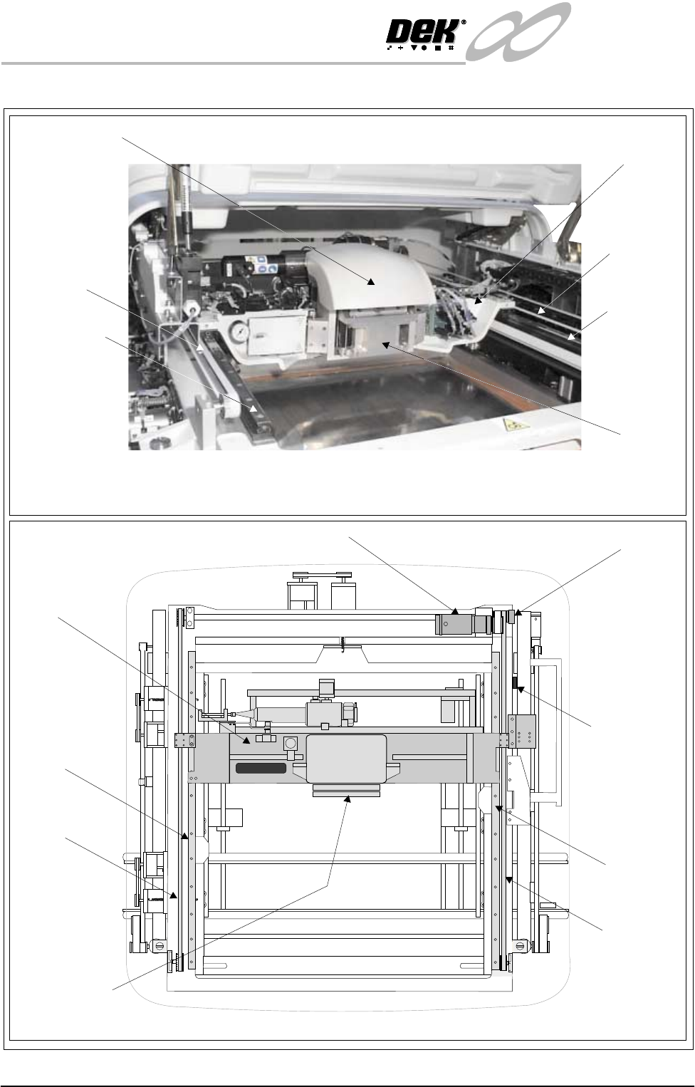
Operation The machine print stroke movement is performed by the print carriage, mounted
on two linear guide rails and driven by a servo motor through a pulley and timing
belt system, (located on the right hand side of the machine).
The home sensor is mounted on the printhead casting near the rear of the right
hand linear guide rail.
The print stroke length is set automatically when the board width is pro-
grammed.
INFINITY
EX
PRINT CARRIAGE MODULE
MODULE OVERVIEW
9.2 Technical Reference Manual Chapter Issue 2 Aug 02
Figure 9-1 Print Carriage Overview
Print Carriage Motor
Print Carriage Brake
Machine Print Carriage Overview (Shroud Covers Removed)
Print Carriage
Casting
Printhead Shroud
Print Carriage
Home Sensor
Front Squeegee
Mounting
Print Carriage
Printhead Plan View
Squeegee
Mounts
Left Timing Belt
Right Timing
Belt
Left Guide Rail
Right Guide
Rail
Left Timing Belt
Right Timing
Belt
Left Guide Rail
Right Guide
Rail
INFINITY
EX
PRINT CARRIAGE MODULE
ELECTRICAL SCHEMATIC
Chapter Issue 2 Aug 02 Technical Reference Manual 9.3
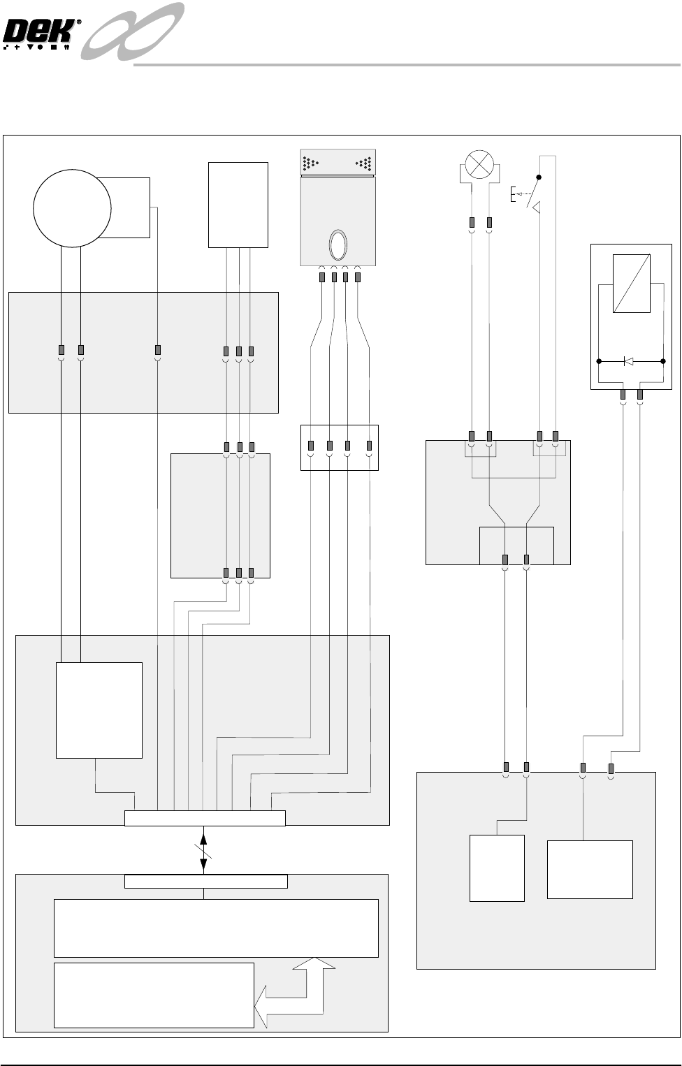
ELECTRICAL SCHEMATIC
Machine Controller
+12v USR
Breakout Board A
+
M
Temperature/Humidity
Sensor (9SE20)
Servo Drive
T
H
APL1
ASK6
Servo 1 Motor +ve
Servo 1 Motor -ve
ADC2
Analog gnd
ADC 4
ye
gn
bu
rd
+12v USR
Machine PC
100 Way
Processor
ISA Bus
NextMove
9SK57
Encoder
(9EN1)
Servo
Motor
(9M2)
Machine Print
Head
9PL37
9SK37
8SK32 8PL32
Print Carriage
Home
9SE3
9SK14
9PL14
8SK32
DigIN6
0v USR
Pin 1
Pin 2
Pin 3
9SK43
9PL43
Breakout Board C
Paste Roll Lamp
(9LP1)
24V (u/s)
CPL8
CPL10
CSK8
CSK10
0v
CSK3
Pin 1
Pin 2
9SK55/9PL55
Paste Roll
Lamp Switch
(8SW4)
Pin 2
Pin 1
CPL3
M24 DC Power Supply Module
Print Carriage
Brake Solenoid
(9SOL03)
9SK36
24V (sw)
0v
Contactor
#2
+24V
M24PL08
M24PL09
1
2
B
A
A
B
X9