Hot-Bump-Pull-Application-Note.pdf
Although these mechanical test methods test the entire assembly , it can howev er be dicult to dierentiate the types of failure modes occurring during the test. Common factors which contribute to dierent failure modes…

Although these mechanical test methods test the entire
assembly, it can however be dicult to dierentiate
the types of failure modes occurring during the test.
Common factors which contribute to dierent failure
modes include:
• Solder metallurgy
• PBAmaterials
• Reowconditions
It is therefore important to isolate the failure modes
in order to identify any weaknesses in the assembly.
is is an important part of development and
production, as it ensures correct design of product,
manufacturing process control as well as quality of
product produced.
Hot Bump Pull/Hot Pin Pull
Application Note
e shift from tin-lead to lead-free materials has had
many aects on the surface mount technology
and printed circuit board industries. ese aects
continue to be a major focus of many sectors from
telecommunications, military, aerospace to consumer
electronics.
A common failure mode in lead-free assemblies is pad
cratering, where the contact pad on a PCB or package
substrate lifts away. ere are many factors that cause this
failure mode to be more prevalent in lead-free assemblies
compared to tin-lead assemblies, these include:
• Lead-free solders are mechanically stier than tin-lead
solders, hence it transfers more strain to the assembly.
• Lead-freesolderrequireshigherreowtemperaturesas
well as cooling rates compared to tin-lead. is can
lead to increased strains on the assembly.
Mechanical testing such as bend and shock testing are
common practices on surface mount assemblies and
printed circuit boards in order to verify product design,
ensure quality and ultimately to ensure product longevity.
e mechanical stresses applied, evaluate the susceptibility
of a product to failure.
Hot Bump Pull/Hot Pin Pull Application Note
What is Hot Bump Pull?
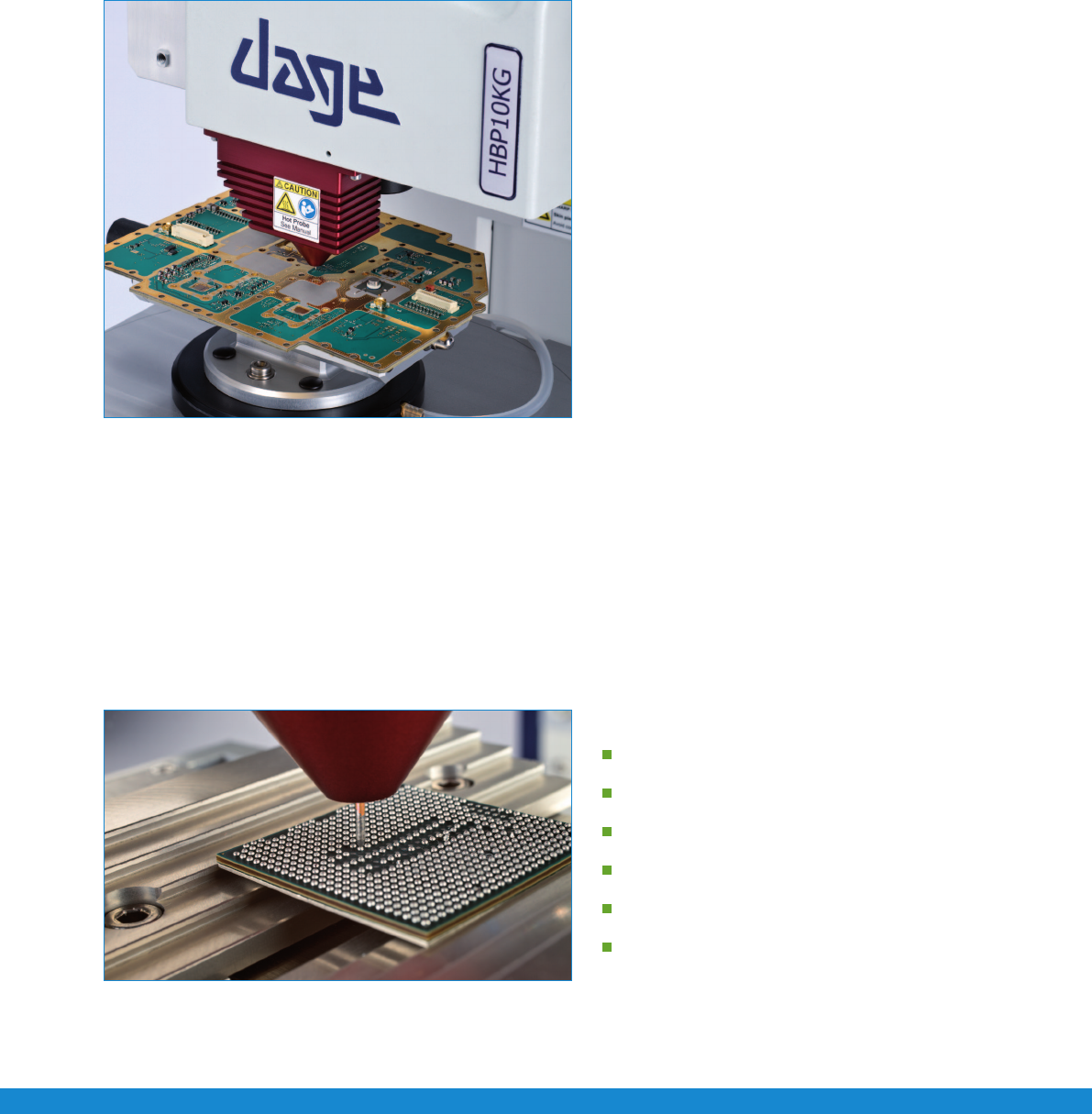
Hot Bump Pull load cartridge
e new Nordson DAGE 4000Plus HBP system is a totally
industry unique solution, conforming to IPC-9708 as well
as JEITA ET-7407A. It is fully integrated into a single load
cartridge on a standard 4000Plus system. Heating, cooling
stages and pin clamping mechanism are integrated into the
single load cartridge. e Paragon
™ software provides a user
friendly interface via temperature time proles to setup a test.
e new cartridge design allow simple straight test pins to
be used, allowing maximum force to be transferred as well as
providing a low cost consumable for testing. e new straight
pin design provides successful and consistent testing.
It is important to pull the pin vertically, directly by the
apparatus without imposing any bending moments.
e latest pad cratering standard, IPC-9708, denes hot bump pull as a method to evaluate the susceptibility of
printed board assembly materials and designs to cohesive dielectric failure underneath surface mount technology
attach pads. A method that can be used to rank order and compare dierent materials and parameters.
The Hot Bump Pull Test Procedure
e test procedure consists of two parts, set up of the test parameters and positioning of the pin over a solder bump.
Firstatemperatureproleiscreated,thisallowsausertoinputtemperatureandtimecriteriaforreowandtestconditions.
is simple interface only requires the desired temperature and the time to reach that temperature. e heating and cooling rates
as well as test execution are then automatically handled by the hardware and software.
A temperature time prole consists of the following stages.
Preheat
Soak
Rate of rise
Reflow/Liquidus
Cool down
Test execution
Close up of copper probe on BGA
Application Note Hot Bump Pull/Hot Pin Pull
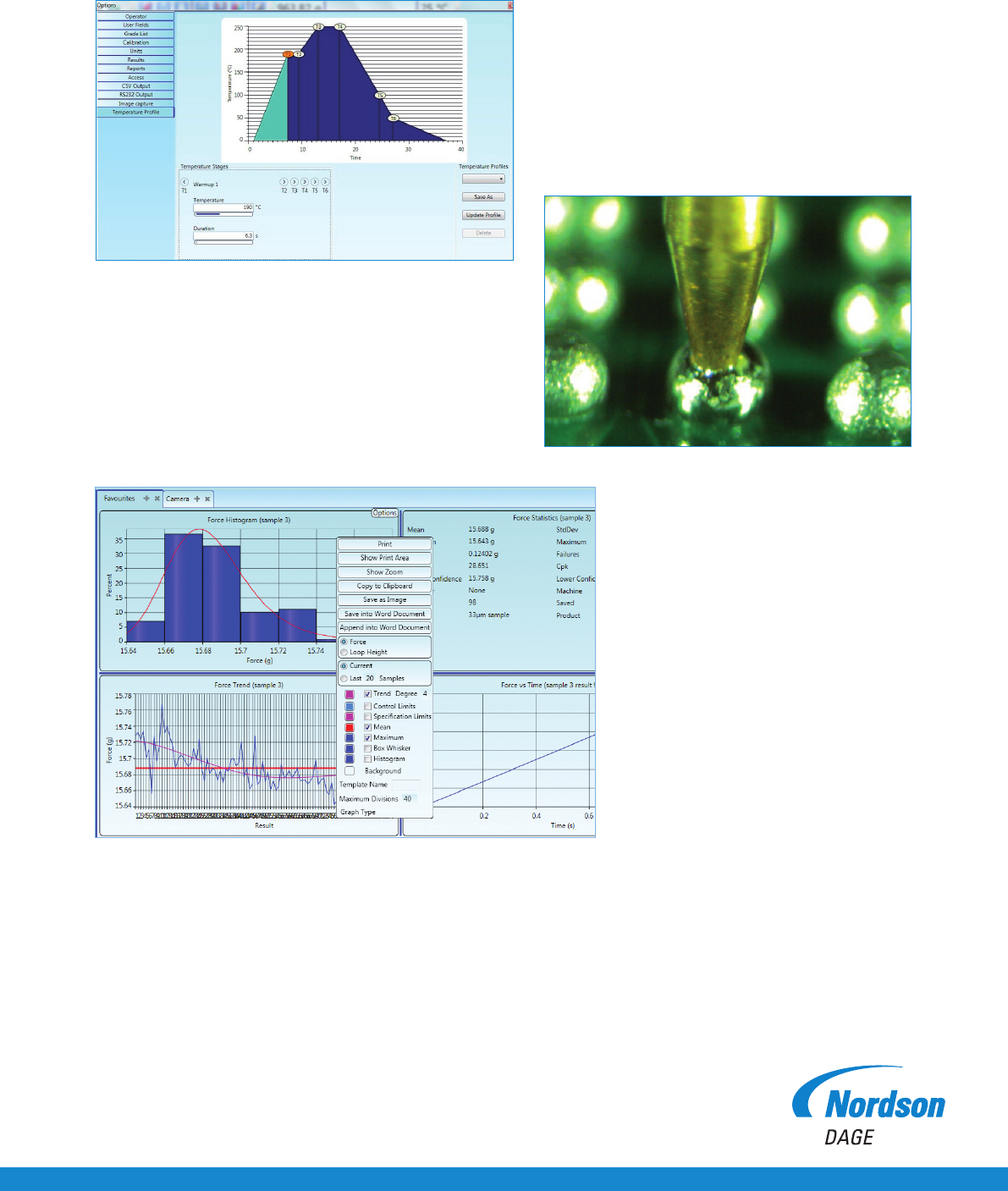
Temperature-time profile in Paragon™
Test results in Paragon™
T1 is the preheat region, this is selected by dening the
temperature to reach and the time to achieve this heating period.
T1 to T2 is the soak period, the soak time can be selected.
T2 to T3 is the rate of rise.
A straight pin is vertically inserted into the cartridge, where it is held in place. e pin is then lowered onto the solder bump via motorised
horizontal and vertical stages. e pin is set so that it is touching the solder bump. e test is then executed, where the pin temperature
rampsupaccordingtothedenedtemperatureprolecreated.Atreowpointthepindropsdowntoadesiredlevel,ensuringagood
solder joint. e clamping mechanism then engages and clamps the pin so it is ready to be pulled. e cooling is handled internally by
pulsing compressed air past the pin and onto the test sample, cooling at the dened temperature prole.
Once the test temperature is reached, the test is automatically executed, recording the force-time,
force-distance and energy values.
T3toT4isthereowperiod,thereow
time period can be selected.
T4 to T5 is the cooling period.
T6 is the temperature where the test will be executed.
Close up of solder ball reflow