Printer 600 Pneumatic Module.pdf
31(80$7,& 02'8/( 02'8/( 29(59,(: Chapter Issue 3 May 03 Technical Reference Manual 24.1 CHAPTER 24 PNEUMA TIC MODULE MODULE OVERVIEW System Descriptio n The mains air supply (at a minimum of 5 bar) is fil…
31(80$7,&02'8/(
02'8/(29(59,(:
Chapter Issue 3 May 03 Technical Reference Manual 24.1
CHAPTER 24 PNEUMATIC MODULE
MODULE OVERVIEW
System
Description
The mains air supply (at a minimum of 5 bar) is filtered and regulated to 5 bar
before being sensed by the air pressure switch, which is set at 3 bar. The
compressed air input is applied to the manifold assembly. The 8 port manifold
has an electrically activated solenoid in each active port, which provides
pneumatic power through several types of air cylinder. Any unused manifold
ports are blanked off.
Air Quality The air should be to quality class 2.3.3, where:
2 (dirt) = 1 micron
3 (water) = -20°C pressure dewpoint
3 (oil) = 1mg/m3
Air Pressure Air should be supplied to the machine at a pressure between 5 bar and 8 bar.
WARNING
COMPRESSED AIR. COMPRESSED AIR SHOULD NEVER IMPINGE UPON THE
BODY. PORTS, PIPES, ETC MUST NEVER BE BLOCKED BY HAND. BEFORE
CONNECTING ANY PNEUMATIC EQUIPMENT TO A COMPRESSED AIR SUPPLY,
ALL MOUNTINGS, FITTINGS, PIPEWORK AND ELECTRICAL CONNECTIONS
SHOULD BE REMOVED FOR SAFETY. NO PIPEWORK ALTERATIONS OR
REMOVAL OF FITTINGS SHOULD BE ATTEMPTED WITH AIR SUPPLIES
CONNECTED.
31(80$7,&02'8/(
02'8/(29(59,(:
24.2 Technical Reference Manual Chapter Issue 3 May 03
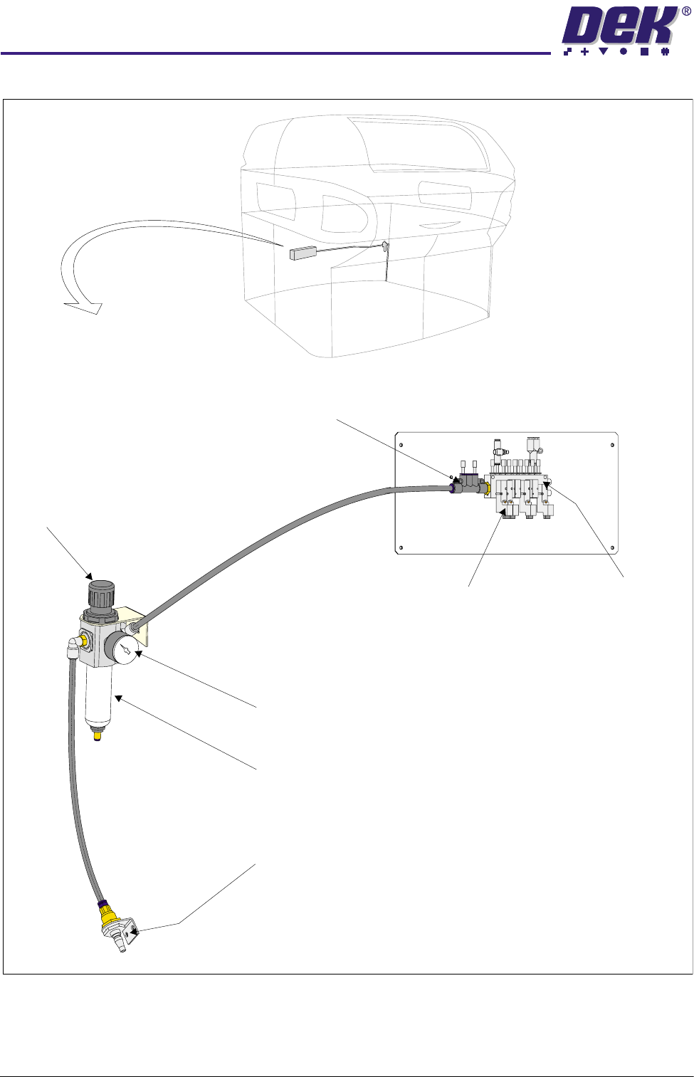
Figure 24-1 Pneumatic Module Overview
Filter
External Connection
Pressure sensor and Gauge
Solenoid Manifold
Manifold
Solenoid Valve
Regulator Assembly
Viewed From Rear of Machine
31(80$7,&02'8/(
31(80$7,&6&+(0$7,&
Chapter Issue 3 May 03 Technical Reference Manual 24.3
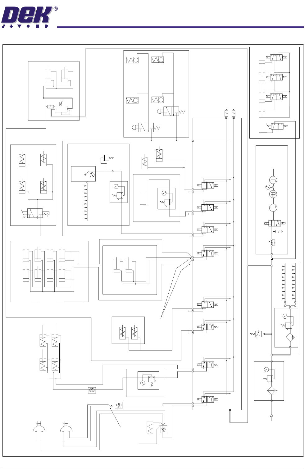
PNEUMATIC SCHEMATIC
Remote Board Stop
(optional)
One connection
made at any
time
One connection
made at any
time
5/2
5/2
5/2
5/2
3/2
3/2
3/2
3/2
Mains Air In
at 4.5 Bar
Minimum
AB
AB
ABAB
A
BA BA BA B
In
In
In
ASM Screen Clamps
Board Clamps
Screen Clean
Squeegee Bar
(optional)
Screen Clamps - Standard
In
Out
Out
In
Out
Out
Out
Lid Bolt
Lid Bolt
Paste Dispense
R
P
Air Ioniser (optional)
Venturi Vacuum (optional)
High Throughput Conveyor
Vacuum
Tooling
Pressure Sensor
Filter/Reg Assy
Filter/Reg Assy
ASM Rail Clamp
Rail Clamps
Left
Screen Clamps
Under Screen
Cleaner (optional)
Wet
Clean
Solvent
Tank
Reg Assy
Reg Assy
Reg Assy
Relief
Valve
Screen Clamps - ELA 0.1 - ELA 0.2
ProFlow + SCAR
(optional)
Rail Clamps
Right
When used
for L-R
Board
Transfer
When used
for R-L
Board
Transfer