Printer 710_810 v8 Adjustable Screen Mount.pdf
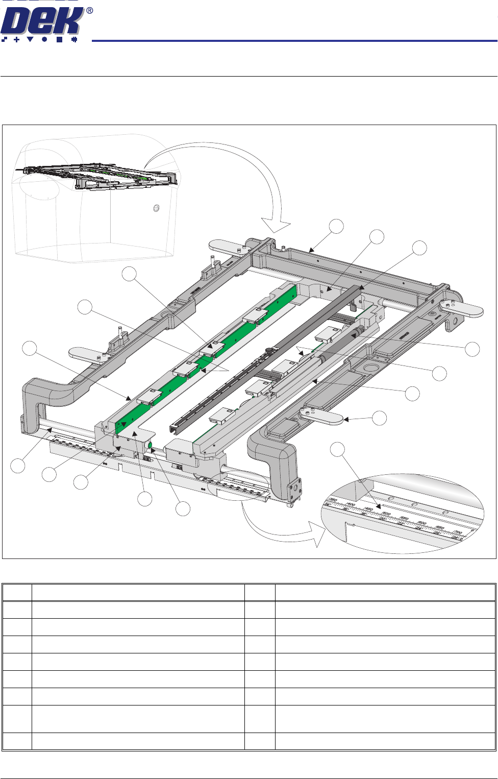
ADJUSTA BLE SCREEN MOUN T (ASM) OVERVIEW Chapter Issue 7 Oct 06 Technical Reference Manual 12.1 CHAPTER 12 ADJUST ABLE SCREEN MOUNT (ASM) OVERVIEW Figure 12-1 ASM Overview Item Desc rip tion Item Desc rip tion 1 ASM Chas…
ADJUSTABLE SCREEN MOUNT (ASM)
OVERVIEW
Chapter Issue 7 Oct 06 Technical Reference Manual 12.1
CHAPTER 12 ADJUSTABLE SCREEN MOUNT (ASM)
OVERVIEW
Figure 12-1 ASM Overview
Item Description Item Description
1 ASM Chase Casting 9 Screen Width Adjustment Release Valve (2 positions)
2 Rear Web Assembly (2 positions) 10 Screen Support Plate (2 positions)
3 Screen Depth Adjuster 11 Front Web Assembly (2 positions)
4 Screen Clamp Pneumatic Cylinder (2 positions) 12 Screen Guide Strip
5 Screen Location Leaf Spring (3 positions) 13 Chase Rail Assembly Guide Shafts (2 positions)
6 Right Hand Chase Rail Assembly 14 Left Hand Chase Rail Assembly
7 Roller Counter Plate (4 positions) 15 Screen at Centre Opto Receiver (transmitter located
in the right hand chase rail assembly)
8 Screen Width Measuring Scale 16 Screen Clamp Assembly (8 positions)
1
2
3
4
5
6
7
8
9
10
11
12
13
14
15
16
ADJUSTABLE SCREEN MOUNT (ASM)
OVERVIEW
12.2 Technical Reference Manual Chapter Issue 7 Oct 06
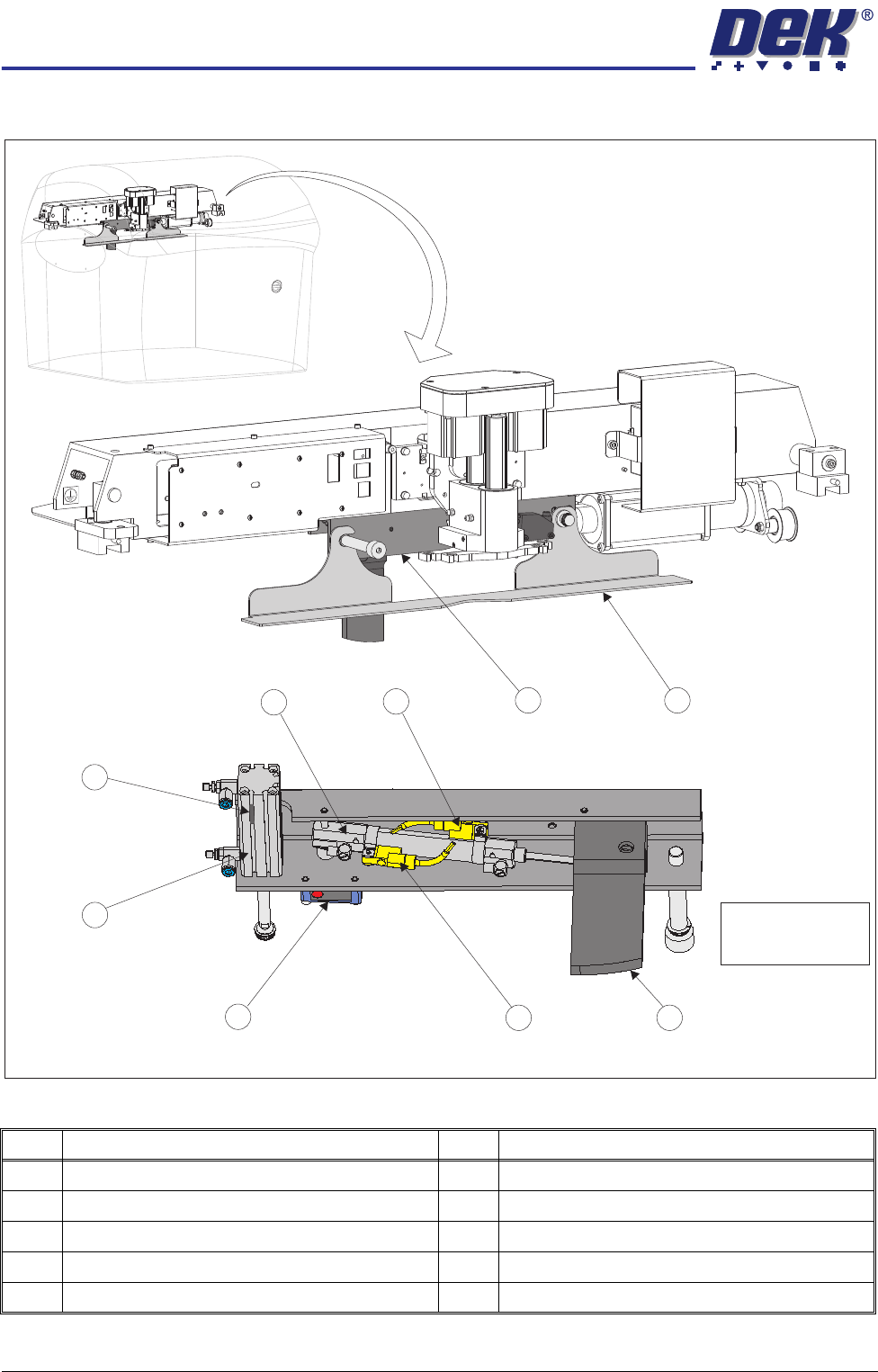
Figure 12-2 Auto Screen Loader Overview
Item Description Item Description
1 Squeegee Drip Tray Mechanism 6 Squeegee Drip Tray Actuator
2 Squeegee Drip Tray 7 Drip Tray Retracted Sensor
3 Auto Screen Loader Lever 8 Auto Screen Loader Actuator
4 Auto Screen Loader Actuator Retracted Sensor 9 Auto Screen Loader Actuator Extended Sensor
5 Screen Position Sensor
1 2
3
4
5
6
7
8
9
View on Rear Underside of Squeegee Drip Tray Mechanism
NOTE
Squeegee drip tray
removed for clarity.

ADJUSTABLE SCREEN MOUNT (ASM)
OVERVIEW
Chapter Issue 7 Oct 06 Technical Reference Manual 12.3
There are three methods for housing and securing the screen in the machine,
the first is a fixed width system and is described in the Cast C Chase chapter,
the second is also a fixed width system and is described in the Machined C
Chase chapter, the third is an adjustable width system and is described in this
chapter.
The ASM module provides a receptacle for the screen, which is clamped in the
correct position for printing operations. The module width can be easily
adjusted by an operator to accommodate screens from the standard 29 inches
square through to 12 inches square with 250mm belt support plates and board
clamps fitted or 29 inches square through to 23 inches square with 500mm belt
support plates and board clamps fitted. The screen image can be front or centre
justified.
The pneumatic push buttons located on the inside of the front left and right hand
web assemblies are operated, releasing all four web assemblies on the front
and rear rail assembly guide shafts. Releasing the web assemblies allows the
user to adjust the position of the left and right hand chase rail assemblies, to
accommodate for the appropriate size screen.
The screen is loaded from the front of the machine and slid into the machine
along the top of stencil support plates. Three screen location leaf springs,
located in the right hand chase rail assembly, ensure that the screen is held in
the correct location for printing, against the screen guide strips on the left hand
chase rail assembly.
The ASM is a floating assembly mounted on a bearing set. The screen is
clamped in the ASM using pneumatically activated flaps that clamp the screen
to the screen support plates.
The ASM is positioned to align the screen to the correct printing position. During
printing the ASM is pneumatically clamped to the left and right printhead
assemblies, to maintain the aligned position, by the screen alignment module
(for further details refer to the Screen Alignment Module chapter in this manual).
A screen at centre, through beam opto (long throw type), sensor consisting of
a transmitter and a receiver (Tx/Rx) is used to detect the presence of a screen
in the ASM.
There are two methods used for achieving correct position of the screen within
the ASM:
• Screen Depth Adjuster
• Auto Screen Loader
NOTE
Only one of the above items would be fitted to the machine at any one time.
Screen Depth
Adjuster
The screen depth adjuster is set by the operator prior to loading the screen. The
screen is loaded manually into the chase until it reaches the stop at the end of
the screen depth adjuster.
NOTE
For further information on setting the screen depth adjuster, refer to Screen
Depth Adjuster in the Adjustments and Settings section of this chapter.