TS934-TS941-user-guide.pdf
12 12. LIMITED WARRANTY Manufacturer warrants this prod uct to the origin al purchaser for a per iod of one (1) year from date of purchase to be free fro m defects in material and workmanship, but not against damages by …
12
12. LIMITED WARRANTY
Manufacturer warrants this product to the original purchaser for a period of one (1)
year from date of purchase to be free from defects in material and workmanship,
but not against damages by misuse, negligence, accident, faulty installations and
instructions. Manufacturer will repair or replace (at factory’s option), free of
charge, any component of the equipment thus found to be defective, on return of
the component, “PREPAID” to the factory during the warranty period. In no event
shall any liability or obligation of the Manufacturer arising from this warranty
exceed the purchase price of the equipment. This warranty is only valid if the
defective product is returned as a complete assembly without physical damage.
The Manufacturer’s liability, as stated herein, cannot be altered or enlarged except
by a written statement signed by an officer of the company. In no event shall the
Manufacturer be liable for consequential or incidental damages. A return
authorization is required from Techcon Systems prior to shipping a defective unit
to the factory.
Manufacturer reserves the right to make engineering product modifications
without notice.
All returns must be issued with a Returns Authorization number, prior to return.
Send warranty returns to:
Americas and Asia
OK International
12151 Monarch Street
Garden Grove, Ca 92841
Europe
OK International
Eagle Close
Chandler’s Ford Ind Est
Eastleigh
Hampshire
SO53 4NF
United Kingdom
www.techconsystems.com
Teflon is a registered trademark of E.I. DuPont.
TSI-0130_H
Techcon Systems
TS934/TS941
TS934A/TS941A
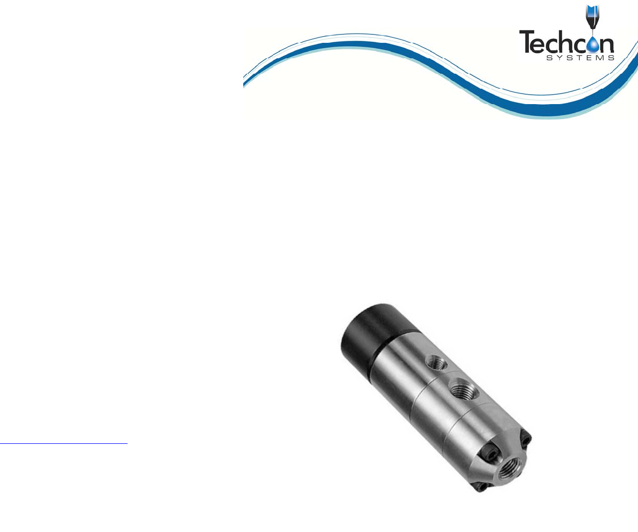
High Pressure Spool Valve
User Guide
2
CONTENTS
Page number
1. Specifications……………..…………………………………………………...3
2. Unpacking and Inspection…….…. ………………………………………..…4
3. Description……..…………………………………………………………..…4
4. Theory of Operation…………………………………………………….….…4
5. Setup Instructions……………………………………………………….….…5
6. Typical System Set-Up..…..…………………………………………….….…5
7. Maintenance and Cleaning……………...…………………………………….6
8. Spare Parts……………….……….…………………………………….…...7-8
9. Repair Kits and Seals…………………………………………………...…….9
10. Accessories…......……………………………………………………………10
11. Troubleshooting..……………………...……………….……….……............11
12. Warranty…………………………………………………….……………….12
11
11. TROUBLESHOOTING
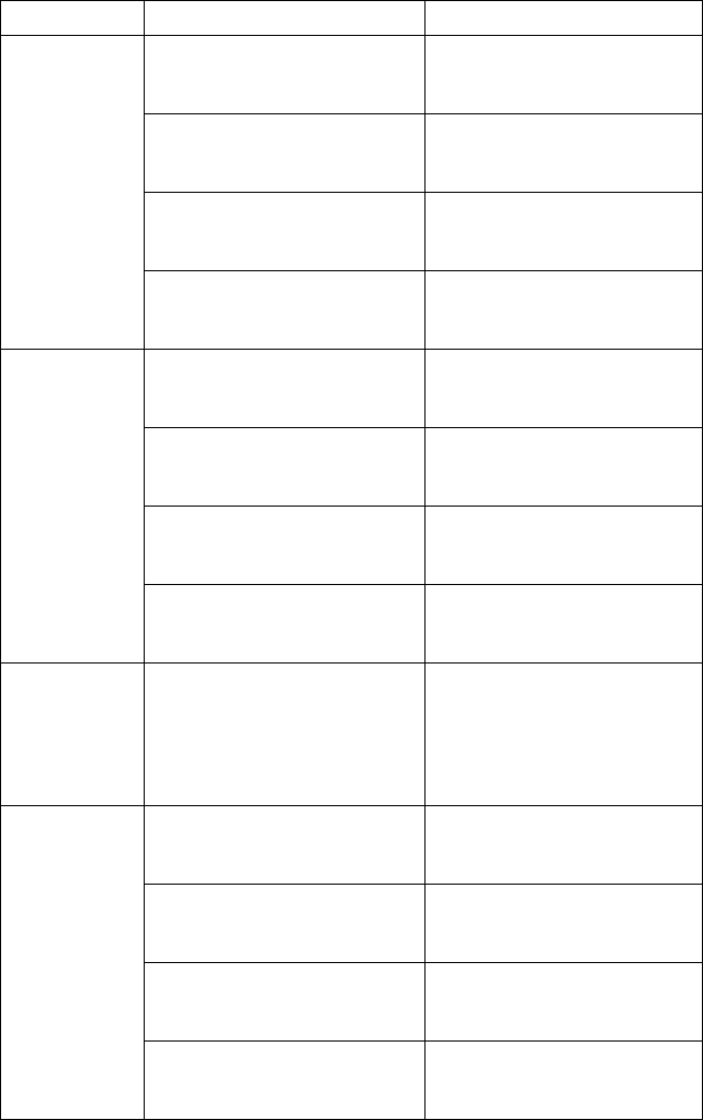
PROBLEM POSSIBLE CAUSE CORRECTION
No fluid flow
Fluid pressure too low Increase fluid pressure
Operating pressure too low
Increase air pressure to 70 psi
(4.8bar)
Dispense tip clogged or
damaged
Replace tip
Fluid cured in valve chamber Clean valve thoroughly
Inconsistent
fluid flow
Fluid pressure fluctuating
Make sure fluid pressure is
constant
Valve operating pressure is too
low
Increased valve pressure to 70
psi (4.8bar)
Valve open time is not
consistent
Check to make sure the valve
controller is providing a
consistent output
Air trapped in fluid housing Purge valve
Fluid drools
after the valve
closes,
eventually
stopping
Air trapped in fluid housing Purge valve
Steady drip
Lower seal damaged or worn Replace lower seal
Spool damaged Replace spool
Inlet air fitting is too long,
pushing the spool opened
Replace air fitting
Valve re-assembled incorrectly
Re-assemble valve, follow re-
assembly instructions
10
10. STANDARD ACCESSORIES
10.1 OPTIONAL ACCESSORIES
10.2 FITTINGS AND TUBINGS
10.3 BRACKETS
PART NUMBER DESCRIPTION
TSD700-1 Oiler Cup
TSD931-15 ¼'' NPT X Female Luer Lock Fitting
TSD918-3 Elbow, ¼-18 NPT X ¼-18 NPT
TSD931-7 Tip Adaptor ¼'' NPT
TSD912-15 Reducer, ⅜'' NPT X ¼'' NPT
TS60C-CON Cleaning Gel, 6oz (177ml)
PART NUMBER DESCRIPTION
918-006-000 Tip adapter, Metal (Nickel Plated Brass)
934-003-000 Adjustable Suck Back Cap
PART NUMBER DESCRIPTION
TSD1002-38 ¼'' NPT to ¼'' O.D. Tube
TSD1566-5 ¼'' NPT to ⅜'' O.D. Tube
TSD1099-22 ⅜'' O.D. X ¼'' I.D. Tube, Black, Polyethylene
TSD1099-23 ⅜'' O.D. X ¼'' I.D. Tube, Clear, Polyethylene
TSD1099-24 ¼'' O.D. X ⅛'' I.D. Tube, Clear, Polyethylene
TSD1099-25 ¼'' O.D. X ⅛'' I.D. Tube, Black, Polyethylene
TSD1099-45 6mm O.D. X 4mm I.D, Clear, Polyethylene
TSD1099-46 6mm O.D. X 4mm I.D, Black, Polyethylene
PART NUMBER DESCRIPTION
918-033-000 Productions Master Stand (Base & Support)
918-000-012 Rod Clamp Assembly
918-000-013 TS934/TS941 Series Spool Valve Bracket
918-000-009 6'' Non-Threaded Mounting Rod
3
1. SPECIFICATIONS
TS934/TS941 TS934A/TS941A
Size
4.7'' length X 1.5'' diameter
(119.4mm X 38.1mm)
4.7'' length X 1.5'' diameter
(119.4mm X 38.1mm)
Weight
TS934 = 1.15lb (522g)
TS941 = 1.6lb (728g)
TS934A = 1.16lb (526g)
TS941A = 1.61lb (731g)
Fluid Inlet
Port
⅜'' NPT female ¼'' NPT female
Fluid Outlet
Port
¼'' NPT female ¼'' NPT female
Air Inlet Port ¼'' NPT female ¼'' NPT female
Auxiliary Air
Inlet Port
⅛'' NPT ⅛'' NPT
Minimum
Air Pressure
70 psi (4.8bar)
70 psi (4.8bar)
Maximum
Fluid
Pressure
2,500 psi (172.4bar) 2,500 psi (172.4bar)
Operating
Frequency
Exceeds 400 cycles/min. Exceeds 400 cycles/min.
Wetted Parts
TS941 Fluid housing = Type 303 SS
TS934 Fluid Housing =Aluminum
Hard Chrome plated Stainless Steel,
UHWPE Seal with EPR O-Ring
TS941A Fluid housing = Type 303 SS
TS934A Fluid Housing = Aluminum
Hard Chrome plated Stainless Steel,
UHMWPE Seal with EPR O-Ring
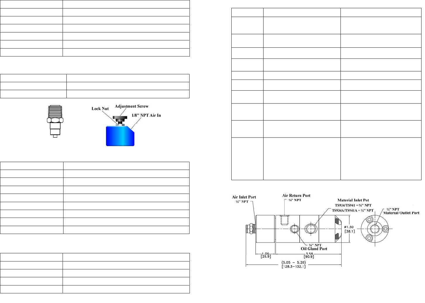
Fi
g
ure 1.0
Dimensions are in inches [mm]