PILOT-NX-V8-XL-UK.pdf
The PI LO T V8 XL N E XT > S E RI ES rep res ent s a u niq ue s olu tio n in the market, in terms of testing area capability united with the vertical architecture. The system maintains all the characteristi cs of the …
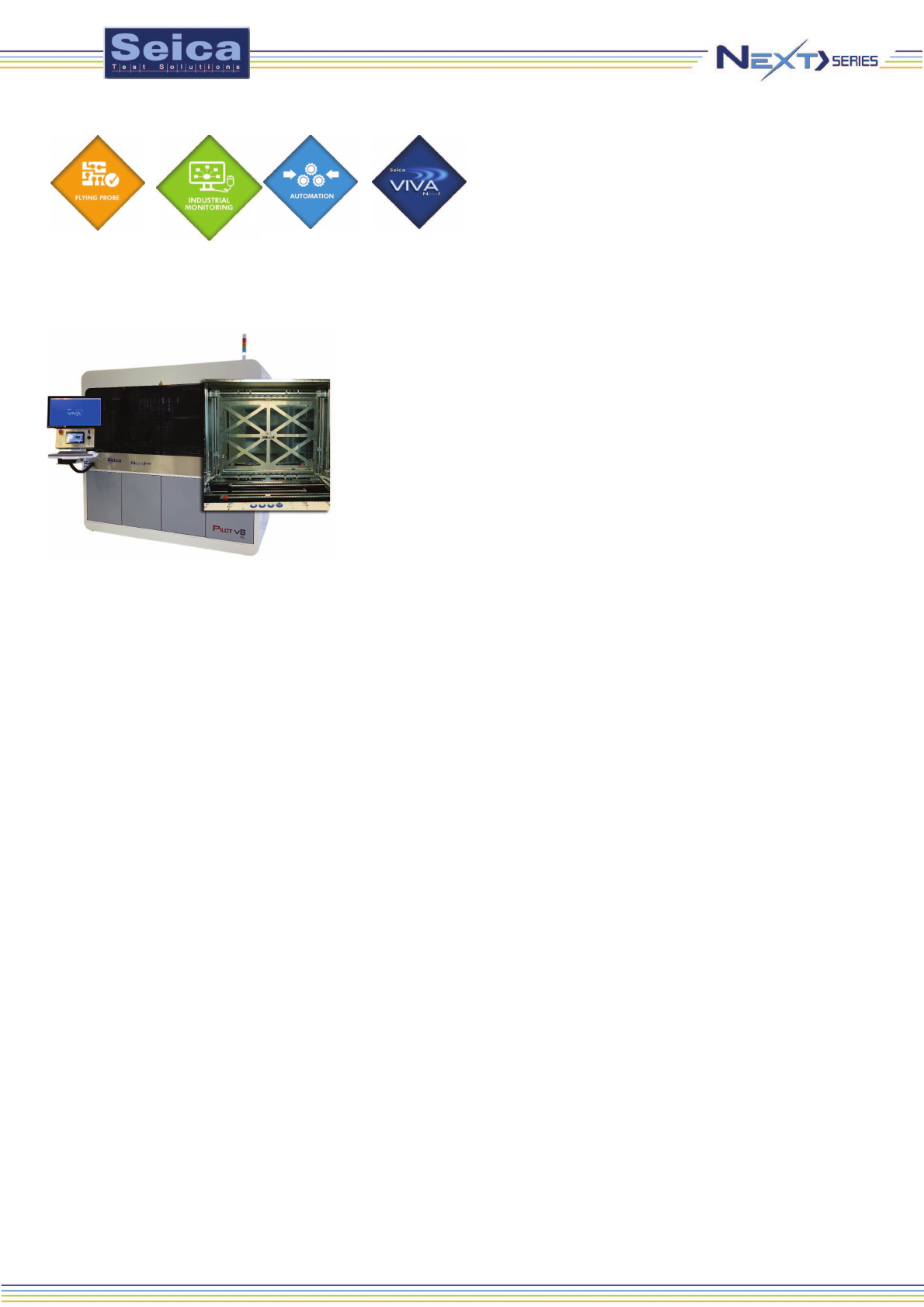
The PILOT V8
XL
NEXT>SERIES represents a unique solution in the
market, in terms of testing area capability united with the vertical architecture.
The system maintains all the characteristics of the consolidated
PILOT V8,
but with a significant increasing of the testing area.
The
PILOT V8
XL
NEXT>SERIES it is the complete solution for those who
produce and test boards with big dimensions, but pretend maximum
performances: the highest test speed, test coverage and flexibility.
Its vertical architecture is the optimum solution for probing both sides of the
UUT simultaneously, becoming a solution for prototyping, manufacturing, or
repairing any type of board. This increases test throughput and flexibility while
guaranteeing fast, precise, reliable and repeatable probing and full availability
of all the mobile resources for testing the UUT. This solution represents an
important technological innovation in double-sided flying probe test, overcoming the intrinsic limitations of horizontal
systems. The
PILOT V8
XL
NEXT>SERIES is equipped with 8 electrical flying test probes (4 on each side), 2 Openfix
flying probes (1 on each side), 2 power flying probes (1 on each side) and 2 CCD cameras (1 on each side), 2 Thermal
Scan sensors, 2 Laser sensors, 2 LED Sensors, for a total of 20 mobile resources available to test the UUT.
• FNODE signature analysis on the nets of the UUT
• Standard analog and digital in-circuit test
• Vectorless tests (AUTIC and OPENFIX), to test ICs for opens
and shorts
• PWMON digital net analysis
• Continuity test to detect open tracks on the PCB
• Visual tests for component presence/absence and rotation
• Optional functional test and boundary scan test
capabilities
• On Board Programming tools for digital devices
• Optional Thermal Scan Resources
• ALI: Automatic Laser Inspection for presence/absence and
warpage compensation
• LED Sensor for light intensity and colour recognition
All of these measurement capabilities and techniques can be
combined in a single test program. Important innovations, such
PILOT V8 XL NEXT>
PILOT NEXT> LINE
as the net-oriented, FNODE and PWMON measurement techniques, provide high fault coverage with significant savings in terms
of programming and test time. In addition, with its full complement of test resources, PILOT V8 NEXT>SERIES
, since it has the capability to operate in all prober
configurations (2 or 4 probes on a single side or on both sides).
NEXT>
Like any other solution, the PILOT V8 NEXT> test system, uses the NEXT> platform, which provides
2 authentication methods managed through the Seica proprietary graphic editor MY VIEW: the standard Windows
authentication and the new ‘VIVA User Authentication’ through which the customer can select the user with different privileges.
Since the customer manages the production and material flow through the MES software, the Seica PILOT V8 NEXT>
can be connected to the customer MES (Manufacturing Execution System). Through its proprietary Adapter, Seica can
integrate all customer MES platforms.
The Information and technology needed to collect and analyze data, is key to the successful digitalization of the manufacturing process, which
is at the heart of the concept. Special attention needs to be given to energy savings and predictive monitoring of events. ,
a Seica Company, introduces ShoeBox, a noninvasive control unit that allows to control energy consumption and to reduce costs and wastes
through Monitoring of consumption, Data analysis, Intervention planning.
SEICA WORLDWIDE
SEICA SpA
via Kennedy 24
10019 Strambino - TO
ITALY
Tel: +39 0125 6368.11
Fax: +39 0125 6368.99
Email: sales@seica.com
PROXIMA S.r.l.
Email: info@proxima-ate.com
SEICA Inc.
Email: DavidSigillo@seicausa.com
SEICA FRANCE SARL
Email: dupoux@seica.fr
SEICA DEUTSCHLAND GmbH
Email: marc.schmuck@seica-
de.com
SEICA ELECTRONICS
(Suzhou) Co.Ltd.
Email: seicachina@seica.com
Seica reserves the right to change the
technical specifications without notice
TDS Pilot Next> series V8 XL vers. 02 UK 03/2021
VIVA NEXT> is available in
a 32 and 64 bit version with a
new graphical interface and a
guided environment for an easy
and quick test program
creation. It is fully integrated
with NI-VISA drivers and with
third-party test management
software.
Probes Position - Test Side Front/Rear
Maximum Number of Resources 20
Number of Electrical Probes 8 (4 front, 4 rear)
Number of Openfix Probes 2 (1 front, 1 rear)
Number of Power Probes 2 (1 front, 1 rear)
Number of Fixed Probes / Upgrade Up To 0/192
Maximum Digital Embedded Channels 4
Number of CCD Colour Cameras 2 (1 front, 1 rear)
Automatic Marker Recognition Yes
Automatic UUT Planarity Compensation Yes
Thermal Scan Module (option) 2 (1 front, 1 rear)
Board Clamping System Manual
Active Test Area 800 x 650 mm (31.5” X 25.50”)
Board Size 802 x 650 mm (31.5” X 25.57”)
Minimum Board Size 100 x 100 mm (0.78 x 0.78")
Maximum Board Thickness 13 mm (0.19") manual
Minimum Board Thickness 1 mm (0.00118")
Board clamping clearance: 10 mm
Board Loading Vertical
UUT Fly Height Clearance Front (mm) Back (mm)
4 x 4 40 40
4 x 2 40 90
4 x 0 40 300
2 x 2 90 90
2 x 4 90 40
0 x 4 300 40
Minimum Pad Pitch 150 µm (6 mil)
Minimum Pad Size 50 µm (2 mil)
Z-axis Travel -3.0 mm to 40 mm programmable
Contact Force 5 g – 150 g programmable
Voltage Generator 1 DC/AC (DRA) ±1 mV to ±10 V (±0.1%)
Voltage Generator 2 DC/AC (DRB) ±1 mV to ±10 V (±0.1%)
Voltage Generator 3 DC/AC (DRC) ±25 mV to ±100 V (±0.2%)
Current Generator DC/AC ±1 nA to ±0.5 A (±0.1%)
Waveform Generator 1 Sin, Tri, Arbitrary (DRA) 1 Hz to 3 MHz (±1 mHz ) - ±10 V max
Waveform Generator 2 Sin, Tri, Arbitrary (DRC) 1 Hz to 10 KHz (±10 mHz ) - ±100 Vmax
Voltage Measurements DC/AC ±200 µV to ±100 V
Current Measurements DC/AC ±3 nA to ±0.5 A
Frequency Measurement 0.1 Hz to 50 MHz
Digital Embedded Channel ±12 V - 500 mA - 10 MHz
Resistance Measurement 1 m to 100 M
Capacitance Measurement 1 pF to 1 F
Inductor Measurement 1 µH to 1 H
Zener Measurement up to 100 V (200V option)
Automatic Visual Inspection Yes
Temperature Range 23°C ± 5°C
Humidity 30 - 80 %
Power 230 V/50 Hz 12 A
110 V/60 Hz 24 A
Power Consumption 2.5 kW max
Air Flow 0.35 CFM - 20l/min.
Weight 1700 kg (3750 Ib)
Length 2060 mm (81.1")
Width 1265 mm (49.8")
Height 1930 mm (76.0"), 2400 mm (94.5") with light-tower
PC/Operating System Windows 10
Software VIVA NEXT
Test Generation Automatic
Autodebug Yes
Data Input Format CAD Data/Manual
Parallel Test Capabilities Yes