N5227B.pdf - 第71页
Find us at www. keysi ght.com Page 71 General Information Table 73 . Miscellaneous Information Description Suppleme ntal Informa tion System IF B andwidth Range 1 Hz to 15 MHz, n ominal CPU For the l atest informati on o…
Find us at www.keysight.com Page 70
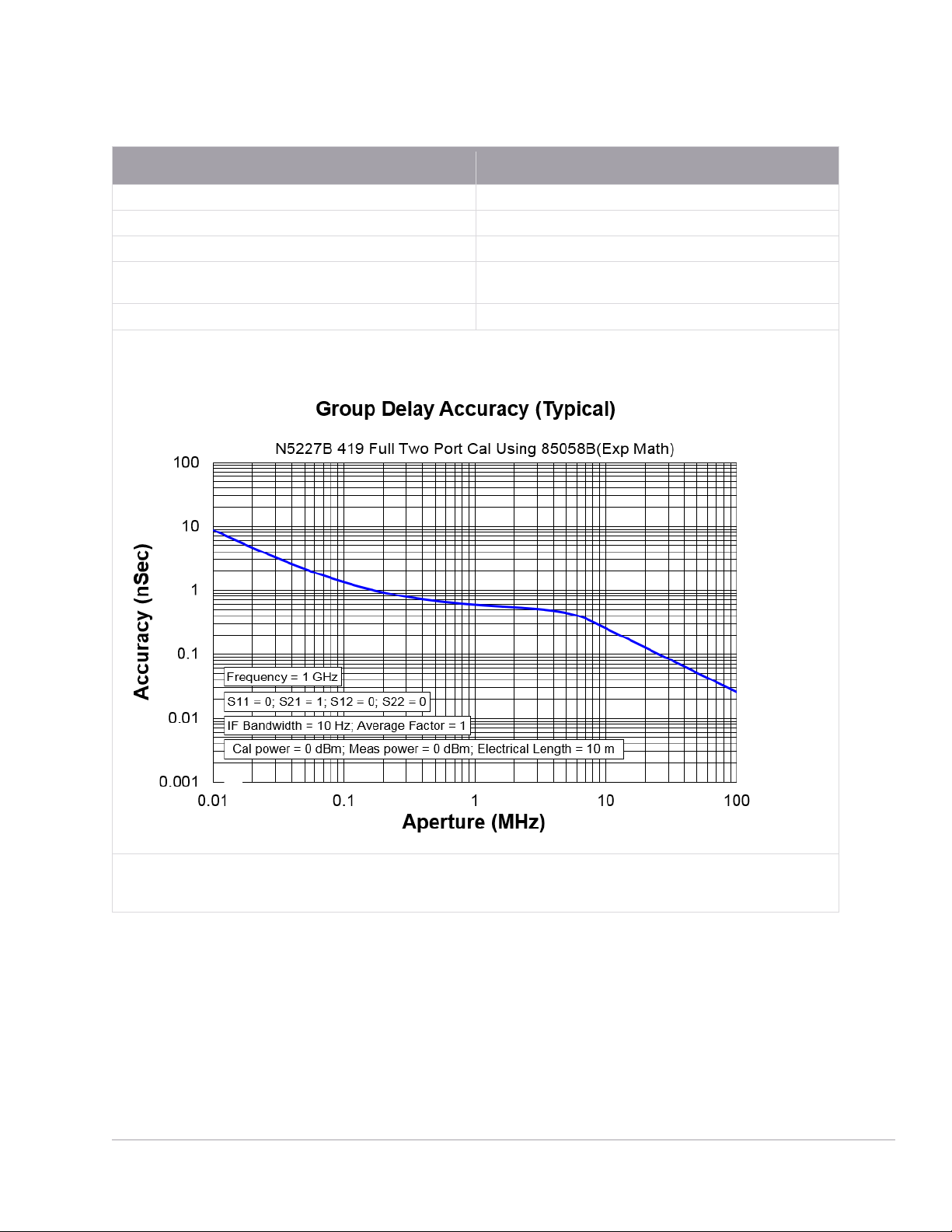
Table 72. Group Delay
1
- Typical
Description Typical Performance
Aperture (selectable)
(frequency span)/(number of points -1)
Maximum Aperture
20% of frequency span
Range
0.5 x (1/minimum aperture)
Maximum Delay
Limited to measuring no more than 180° of phase change within the
minimum aperture.)
Accuracy
See graph below. Char.
The following graph shows characteristic group delay accuracy with full 2-port calibration and a 10 Hz IF bandwidth. Insertion loss is
assumed to be < 2 dB and electrical length to be ten meters.
For any S
ij
Group Delay measurement, S
ii
= 0, S
ij
= 1, S
ji
= 0, S
kl
= 0 for all kl ≠ ij
In general, the following formula can be used to determine the accuracy, in seconds, of specific group delay measurement:
±Phase Accuracy (deg)/[360 × Aperture (Hz)]
Depending on the aperture and device length, the phase accuracy used is either incremental phase accuracy or worst-case phase accuracy.
1
Group delay is computed by measuring the phase change within a specified frequency step (determined by the
frequency span and the number of points per sweep).

Find us at www.keysight.com Page 71
General Information
Table 73. Miscellaneous Information
Description Supplemental Information
System IF Bandwidth Range
1 Hz to 15 MHz, nominal
CPU
For the latest information on CPUs and associated hard drives, visit: PNA Hard Drives
and CPUs (keysight.com)
LXI
CPU version 7.0, 8.0
CPU version 9.0
Class C
LXI 1.5
Extended Functions:
HiSLIP; VSI-11 Discovery and
Identification
Maximum Number of Points
100003
Table 74. Front Panel Information, All Options
Description Typical Performance
RF Connectors
Type
1.85 mm (male), 50 ohm, (nominal)
Center Pin Recession
0.002 in. (characteristic)
USB 2.0 Ports - Primary (4 ports)
Standard
Compatible with USB 2.0
Connector
USB Type-A female
Display
Size
31 cm (12.1 in) diagonal color active matrix LCD; 1280 (horizontal) X 800 (vertical)
resolution
Refresh Rate
Vertical 60 Hz; Horizontal 49.31 kHz
Pixels
Any of the following would cause a display to be considered faulty:
• A complete row or column consists of “stuck” or “dark” pixels.
• More than six “stuck on” pixels (but not more than three green) or more than 0.002%
of the total pixels are within the LCD specifications.
• More than twelve “dark” pixels (but no more than seven of the same color) or more
than 0.004% of the total pixels are within the LCD specifications.
• Two or more consecutive "stuck on" pixels or three or more consecutive "dark" pixel
(but no more than one set of two consecutive dark pixels).
• “Stuck on” pixels or more than two “dark” pixels less than 6.5 mm apart (excluding
consecutive pixels).

Find us at www.keysight.com Page 72
Description Typical Performance
Display Range
Magnitude
±2500 dB (at 500 dB/div), max
Phase
±2500° (at 500 degrees/div), max
Polar
10 pUnits, min
10,000 Units, max
Display Resolution
Magnitude
0.001 dB/div, min
Phase
0.01°/div, min
Marker Resolution
Magnitude
0.001 dB, min
Phase
0.01°, min
Polar
10 pUnit, min
Table 75. Rear Panel Information, All Options
Description Typical Performance
10 MHz Reference In
Connector
BNC, female
Input Frequency
10 MHz ±1 ppm, 100 MHz ±1 ppm
20 MHz ±1 ppm, 80 MHz ±1 ppm
Input Level
10 MHz: -15 dBm to +20 dBm
100 MHz: -10 dBm to +20 dBm
Input Impedance
50 Ω, nom.
10 MHz Reference Out
Connector
BNC, female
Output Frequency
10 MHz ±0.7 ppm, 100 MHz ±0.7 ppm
Signal Type
Sine Wave
Output Level
+10 dBm ±4 dB into 50 Ω
Output Impedance
50 Ω, nominal
Harmonics
<-40 dBc, typical
External IF Inputs
Function
Allows use of external IF signals from remote mixers, bypassing the PNA's first converters
Connectors
SMA (female); A, B, C, D, R (4-port); A, B, R1, R2 (2-port)
Input Frequency
Normal IF path
Narrowband IF path
RF < 53 MHz: IF = 826.446 KHz
RF >= 53 MHz: IF = 7.438 MHz
IF = 10.70 MHz
Input Impedance
50 Ω
RF Damage Level
+23 dBm
DC Damage Level
5.5 VDC