00193463-01 - 第104页
3 What to do when .. . User Manual SIPLACE S-25 HM 3.1 Switching on the SIPLACE line Software Version SR.503.xx 04/2002 US Edition 104 3.1.4 Switc hin g on the station/starting the user interf ace of t he st ation comput…
User Manual SIPLACE S-25 HM 3 What to do when ...
Software Version SR.503.xx 04/2002 US Edition 3.1 Switching on the SIPLACE line
103
3
Fig. 3.1 - 1 Starting SIPLACE Pro
3.1.3 What you should check before switching on the stations
ATTENTION
Carry out the steps described in the following before you switch on the stations. 3
Æ Check to make sure that the stations are connected to power and to the compressed air supply.
Æ Carry out a visual inspection of the stations. In particular, make sure that there are no obstruc-
tions in the traveling range of the gantries.
Æ Make sure that the Z-axes of all the heads are in the top end position.
Æ Close the feeder covers and the protective covers.
Æ Make sure that there is no diskette in the floppy drive of the station computer.
3 What to do when ... User Manual SIPLACE S-25 HM
3.1 Switching on the SIPLACE line Software Version SR.503.xx 04/2002 US Edition
104
3.1.4 Switching on the station/starting the user interface of the
station computer program
ATTENTION
Switch on the station only after the desktop is displayed on the line computer monitor. Otherwise,
communication problems may occur. 3
Æ Switch on the station on the main switch and check to see if the manometer displays the re-
quired operating pressure after you have switched the station on.
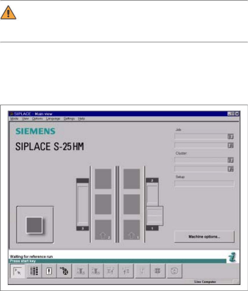
The station computer software is uploaded. When the line computer is connected and commu-
nication is error-free, the Main view of the station computer user interface appears for the "Op-
erator" user class after approximately 2 minutes (see Fig. 3.1 - 2).
Fig. 3.1 - 2 Main view after loading the station computer software

User Manual SIPLACE S-25 HM 3 What to do when ...
Software Version SR.503.xx 04/2002 US Edition 3.1 Switching on the SIPLACE line
105
NOTE
The current state of the station is displayed in the status field in the "State" line, and the action you
are to execute is displayed in the "Action:" line (see Fig. 3.1 - 2). 3
Æ Press one of the start keys (white) when prompted with "Press start key".
(The start keys are located on the input side and output side of the placement system.)
A reference sequence is executed on all axes. The station is ready for operation after the ref-
erence sequence has completed.
The symbol is displayed in the work area of the user interface.
3.1.5 "Switching on the SIPLACE line" flow chart
The following flow chart shows the actions executed be the line computer, station and operator while
the SIPLACE line is being switched on and started up.