00193463-01 - 第109页
User Manual SIPLACE S-25 HM 3 What to do when ... Software Vers ion SR.503.xx 04/2002 US Edition 3.3 Changing jobs 109 3.3 Changing j obs Æ Inte rrupt t he job de fined f or the st ation on the line co mpute r using the …

3 What to do when ... User Manual SIPLACE S-25 HM
3.2 Switching off the SIPLACE line Software Version SR.503.xx 04/2002 US Edition
108
3.2.2 Shutting down SIPLACE Pro (Windows NT)
Æ From the SIPLACE Pro menu bar, click on the ‘Object’ pop-up menu, then on the ‘Exit’ option.
Æ Close all other programs running on the computer.
Æ Click on ‘Exit’ from the Windows Start menu.
3.2.3 Switching off the stations
Proceed as follows to switch off the station:
Æ Terminate all placement operations.
Æ Check to make sure that the Z-axes of all placement heads are in the upper end position.
Æ Check to see if there are still components in the placement heads and remove any components
found.
Æ If necessary, move all gantries to the standby position with the help of the corresponding gantry
functions.
NOTE
All gantries are normally moved to the standby position automatically. 3
Æ Shut down the operating system on your station computer.
Æ Now switch off the station on the main switch.
3.2.4 Starting stations that remain switched on after the line computer
has been shut down
If stations remain switched on after the line computer has been shut down and the line computer
is then restarted, the computer will establish connections with these stations (synchronous
restart).
User Manual SIPLACE S-25 HM 3 What to do when ...
Software Version SR.503.xx 04/2002 US Edition 3.3 Changing jobs
109
3.3 Changing jobs
Æ Interrupt the job defined for the station on the line computer using the function (Interrupt).
Æ Enter the new job on the line computer using the function (Schedule).
Æ Check the width of the conveyor belt.
Æ Check the position of the magnetic supports and make sure that they cannot collide with com-
ponents on the bottom of the PCB.
Æ Carry out the set-up check.
Make sure that the feeder modules are equipped with the correct components and that the
feeder modules are at the correct locations.
Æ Check the nozzle configuration in the nozzle changer.
If no nozzle changer is installed, then you must change the nozzles manually.
NOTE
If you change the nozzle manually, ALWAYS make sure that you are using the correct nozzle
type and that the nozzle is seated correctly on the spindle. (The plunger pin must click into
place in the notch slot of the nozzle).
If you have not inserted a nozzle or have used the wrong nozzle type, then the station com-
puter program will prompt you to move the placement head to the service position and
change the nozzle. This error message will also appear if you have not inserted the nozzle
correctly.
If you insert the wrong nozzle or use the wrong nozzle type again, then the gantry will move to
the service position once more after the reference sequence. The station computer program
will continue to prompt for a nozzle change until you have obtained the correct configuration.
If you do not succeed, then proceed as follows:
Æ Switch off the station and cancel the specified job on the line computer.
Æ Rectify the nozzle error and restart the station.
TIP
Have the nozzles ready in a separate nozzle box in which each compartment is labeled with the
type and color of the nozzle. This will help to prevent confusion. Do not save used plastic nozzles,
dispose of them immediately instead. 3
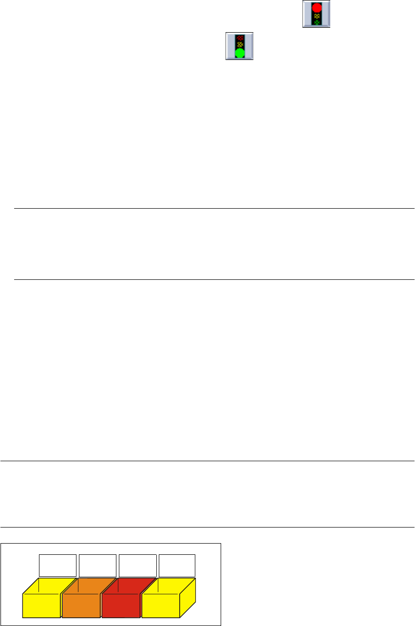
Fig. 3.3 - 1 Example of a nozzle box
701
yellow
704
orange
705
red
711
yellow

3 What to do when ... User Manual SIPLACE S-25 HM
3.4 When you change shift Software Version SR.503.xx 04/2002 US Edition
110
3.4 When you change shift
Æ Splice the tapes early enough so that the feeder modules do not have to be refilled as soon as
the new shift starts. This will prevent lead to pick-up errors and prolonged down times.
Æ Inform the next operator of any important information when changing shifts when, for example,
something has been changed in the placement program or if errors have occurred more fre-
quently in certain feeder modules. Also read through the list of the descriptions of the steps to
take in section 3.6.
Æ Carry out a set-up check.
Make sure that the feeder modules are equipped with the correct components and that they
are at the correct locations in the component table.
NOTE
Hand over the line in the same state that you would want to find it in when starting your shift.
This means that:
- The rejection containers are empty.
- The waste containers are empty.
- The conveyor areas have been cleaned with a vacuum cleaner.
- Defective feeder modules in the feeder area have been replaced. 3