00193463-01 - 第141页
User Manual SIPLAC E S-25 HM 4 Component han dling Software Vers ion SR.503.xx 04/2002 US Edition 4.3 Setting up the feeders 141 4.3 Setting up the feeders 4.3.1 Prep a ring the component t able and feeder for set-up Æ S…

4 Component handling User Manual SIPLACE S-25 HM
4.2 Technical data for the feeders Software Version SR.503.xx 04/2002 US Edition
140
4.2.11.2 Technical data
4
4
4
4
4
4
4.2.11.3 Parameters for the surftape feeders
The parameters for the surftape feeders can be modified on the line computer.
4
Tape widths 8/12/16 mm
Recommended tape and component
sizes
8 mm: 1 x 1 mm – 2.3 x 2.3 mm components
12 mm: 2.3 x 2.3 mm - 5 x 5 mm components
16 mm: 3.8 x 3.8 mm -9.5 x 9.5 mm components
Packaging accuracy of the bare die on
the surf tape
Bare die sizes up to 2.3 x 2.3 mm: +/- 100 µm, 6
σ
Bare die sizes over 2.3 x 2.3 mm: +/-200 µm, 6 σ
(in relation to the center of the pocket)
Required distance between the edges of
the bare dies to the tape pocket Min. 0.4 mm
Pusher needle Single or triple needle depending on the die size
Tape material Metric
Tape standard IEC 286-3, DIN-IEC-286, EIA 481 and JIS C 0806
Tape reel diameter 7" to 15"
Feeder footprint 1 track on the component feeder table

User Manual SIPLACE S-25 HM 4 Component handling
Software Version SR.503.xx 04/2002 US Edition 4.3 Setting up the feeders
141
4.3 Setting up the feeders
4.3.1 Preparing the component table and feeder for set-up
Æ Select the setting range for the feeder to be used
(see Vibrator configuration).
Æ Move the placement head to the waiting position and press the emergency stop button.
Æ Open the protective covers.
Æ Clean the contact surface for the feeders and the contact surface for the feeders on the com-
ponent table.
Æ Place the feeder on the previously selected track on the component table (see Vibrator config-
uration).
4.3.2 Insert the feeder
Æ Insert the feeder so that the back of the feeder is held by the centering ball and the front is fixed
in place by the corresponding centering pin on the component table. Make sure that the feeder
is placed on the component table in the correct position for its width.
Æ Check that the feeder is firmly seated on the component table.
Æ Connect the feeder plug to the socket beneath the location.
PLEASE NOTE 4
When you connect the feeder, make sure that you use the right socket for the location since
the feeder receives the control pulse via this socket. The feeder may not work correctly if it is
not connected to the right socket. 4
Æ Close the protective covers and switch the control on again.
Æ Carry out a refill check if necessary.
Æ Continue placement.
4 Component handling User Manual SIPLACE S-25 HM
4.3 Setting up the feeders Software Version SR.503.xx 04/2002 US Edition
142
4
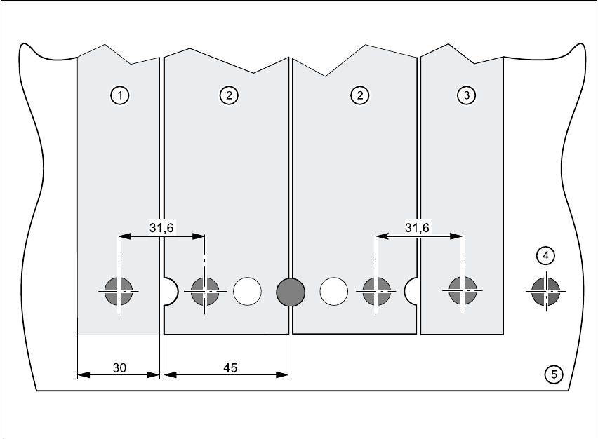
Fig. 4.3 - 1 Inserting 30 or 45 mm wide feeders on the component table
(1) Feeder, 30 mm wide
(2) Feeder, 45 mm wide
(3) Feeder, 30 mm wide
(4) Centering ball
(5) Component table