00193463-01 - 第151页
User Manual SIPLAC E S-25 HM 4 Component han dling Software Version SR.503.xx 04/2002 US Edition 4.7 Matrix tray changer 151 4.7 Matrix tray changer 4.7. 1 Ove rview Fig. 4.7 - 1 Matrix tray changer, back view (1) Main s…
4 Component handling User Manual SIPLACE S-25 HM
4.6 Component table, mobile Software Version SR.503.xx 04/2002 US Edition
150
4.6.3 Docking the component table
WARNING 4
Check that the placement head is outside the range of the component table. 4
CAUTION 4
When docking the component table, ensure that the table bed is in its top end position and the
bracket (item 7) is folded up. 4
Æ Cut off the empty tapes for the feeders.
Æ Make sure that the contact surface (item 10) for the component table bed is clean.
Æ CAREFULLY push the component table into the placement system.
Æ Connect the compressed air supply (item 3).
Æ Plug in the control cable (item 1).
Æ Move the cover (item 12) over the control cable plug to expose the power supply socket.
Æ Plug in the power cable (item 2) for the component table.
Æ Pull the two actuating tubes (item 6) towards you at the same time and then lower the bracket
(item 7) in order to be able to lower the component table bed.
Æ Check that the centring holes in the component table bed lie precisely over the centering pins
of the placement system.
Æ Hold down the button (item 5) until the component table bed reaches its top end position.
Æ Release the button and the component table bed will descend.
Æ Ensure that the centring pins engage in the centring holes in the component table bed and that
the component table bed is fully lowered.
Æ Fold up the bracket (item 7) of the component table.
Æ Lock the two horizontal tensioners (item 11).
Æ Close the side screens and protective cover.
Æ Press the Start button to start the placement system.
4
4
User Manual SIPLACE S-25 HM 4 Component handling
Software Version SR.503.xx 04/2002 US Edition 4.7 Matrix tray changer
151
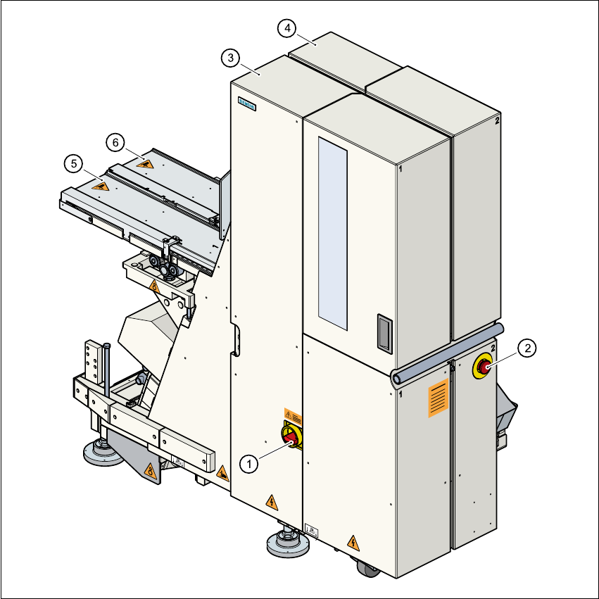
4.7 Matrix tray changer
4.7.1 Overview
Fig. 4.7 - 1 Matrix tray changer, back view
(1) Main switch
(2) Emergency stop mushroom-head push-button
(3) Tower 1 for up to 40 waffle trays
(4) Tower 2 for up to 40 waffle trays
(5) Feed axis 1
(6) Feed axis 2

4 Component handling User Manual SIPLACE S-25 HM
4.7 Matrix tray changer Software Version SR.503.xx 04/2002 US Edition
152
4.7.2 General
The use of flatpack ICs is becoming an increasingly significant aspect in the production of flat
modules. These components are now almost exclusively provided in waffle trays.
The space required by waffle trays is relatively large in comparison to the component density,
however.
The low component capacity also requires the waffle trays to be changed frequently, which
means that the placement sequence has to be interrupted if the trays are changed manually.
The use of a matrix tray changer eliminates this unnecessary time loss since the waffle trays are
stored and automatically changed. Programmable, random access to up to 2 x 40 waffle trays
also increases the range of components that can be made available.
PLEASE NOTE: 4
The matrix tray changer can be coupled at location 1 on the right-hand side of the machine and/
or at location 3 on the left-hand side of the machine. It does not take up the whole width of a
location. The component feeder table integrated into the matrix tray changer (see item 2 in Fig.
4.7 - 2) has a capacity of 9 feeder locations. 4