00193463-01 - 第153页
User Manual SIPLAC E S-25 HM 4 Component han dling Software Version SR.503.xx 04/2002 US Edition 4.7 Matrix tray changer 153 Fig. 4.7 - 2 Matrix tray changer , front view (1) T ape container (2) Integral componen t feede…

4 Component handling User Manual SIPLACE S-25 HM
4.7 Matrix tray changer Software Version SR.503.xx 04/2002 US Edition
152
4.7.2 General
The use of flatpack ICs is becoming an increasingly significant aspect in the production of flat
modules. These components are now almost exclusively provided in waffle trays.
The space required by waffle trays is relatively large in comparison to the component density,
however.
The low component capacity also requires the waffle trays to be changed frequently, which
means that the placement sequence has to be interrupted if the trays are changed manually.
The use of a matrix tray changer eliminates this unnecessary time loss since the waffle trays are
stored and automatically changed. Programmable, random access to up to 2 x 40 waffle trays
also increases the range of components that can be made available.
PLEASE NOTE: 4
The matrix tray changer can be coupled at location 1 on the right-hand side of the machine and/
or at location 3 on the left-hand side of the machine. It does not take up the whole width of a
location. The component feeder table integrated into the matrix tray changer (see item 2 in Fig.
4.7 - 2) has a capacity of 9 feeder locations. 4
User Manual SIPLACE S-25 HM 4 Component handling
Software Version SR.503.xx 04/2002 US Edition 4.7 Matrix tray changer
153
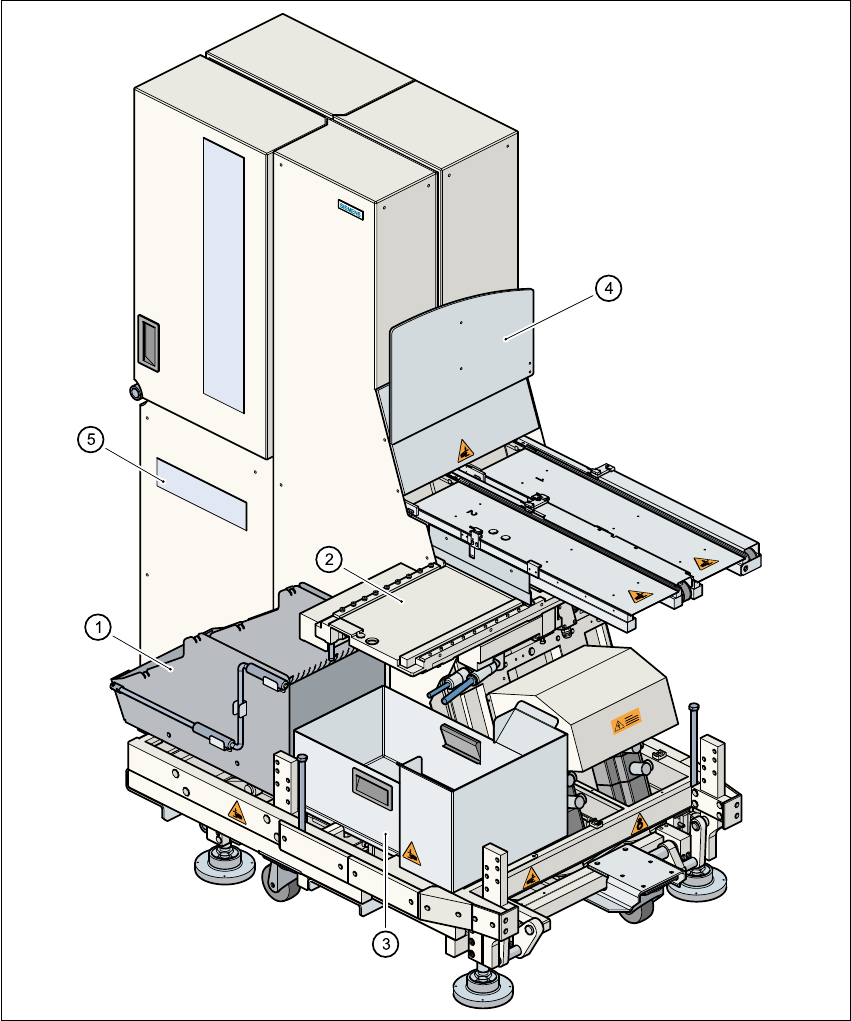
Fig. 4.7 - 2 Matrix tray changer, front view
(1) Tape container
(2) Integral component feeder table with 9 locations
(3) Waste tape container
(4) Guard for the inside of the SIPLACE machine
(5) Display panel for statuses, warning and faults

4 Component handling User Manual SIPLACE S-25 HM
4.7 Matrix tray changer Software Version SR.503.xx 04/2002 US Edition
154
4.7.3 Principle of the matrix tray changer
The matrix tray changer can be used to store and change up to 80 waffle trays fully automatically.
The levels (storage locations in the towers) for the waffle trays are numbered consecutively in
ascending order from bottom to top.
The towers move independently of one another in the vertical direction until the selected
magazine is within range of the feed axis. The feed axis transports the waffle tray from the tower
into the access area of the placement head.
4.7.4 Technical data, matrix tray changer
4.7.4.1 Dimensions, weight, other data
4
4
4
4
Dimensions (L x W x H) 1350 mm x 775 mm x 1499 mm
Weight (basic equipment) approx. 500 kg (incl. cassettes and waffle pack
tray carriers)
Weight (partly equipped) approx. 532 kg (including components)
Weight (fully equipped) approx. 600 kg (incl. tape reels and feeders)
Weight (moved mass) approx. 43.5 kg per tower
Cassette size (L x W x H) 354.1 mm x 154.8 mm x 131 mm
Weight of cassette approx 7.5 kg
Vertical stroke 502.5 mm (1st to 40th waffle pack tray carrier)
Horizontal stroke approx. 640 mm (between reference position and
component position)
Spacing from one level to next 11 mm
Spacing from one cassette to next 134.5 mm
Storage capacity 80 waffle pack tray carriers for waffle pack maga-
zines
Waffle pack tray carrier
Size (L x W x H)
Changeover time (over 5 levels)
371 mm x 146 mm x 10.1 mm
2 s
Load per unit area on mounting foot/roll 2.78 kg/cm²
or 4.01 kg/cm² (fully equipped)
Minimum component size (L x W) 5 mm x 5 mm
Maximum component size 15.5 mm (When using components larger than
7.62 mm remove every second waffle pack tray
carrier)