00193463-01 - 第183页
User Manual SIPLAC E S-25 HM 5 Station extensions Software Vers ion SR.503.xx 04/2002 US Edition 5.5 Ceram ic substrate ce ntering 183 5.5.4 T echnical dat a 5.5.5 Optical centering with oblique lighting 5.5.5.1 General …
5 Station extensions User Manual SIPLACE S-25 HM
5.5 Ceramic substrate centering Software Version SR.503.xx 04/2002 US Edition
182
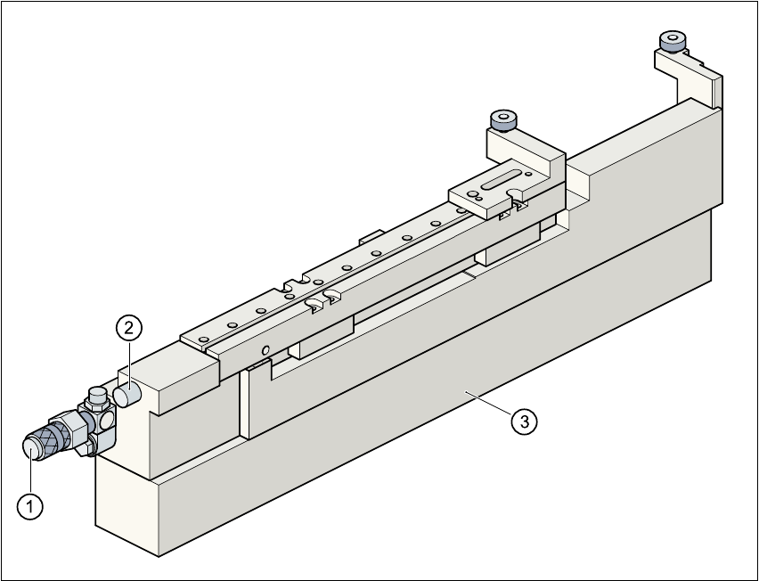
Fig. 5.5 - 2 Ceramic substrate centering (side view)
(1) Connecting nozzle
(2) ‘Ceramic substrate centering’ sensor
(3) Base
5.5.3.3 Maintenance
– Clean and grease the ball race in the X-axis centering unit.
– If necessary, check that the pneumatic driving mechanism is running smoothly.
– The conveyor should be maintained as described in the maintenance instructions.
User Manual SIPLACE S-25 HM 5 Station extensions
Software Version SR.503.xx 04/2002 US Edition 5.5 Ceramic substrate centering
183
5.5.4 Technical data
5.5.5 Optical centering with oblique lighting
5.5.5.1 General
For optical centering, the special features of the ceramic substrate must be taken into account.
The contrast depends very much on the paste used for the adjustment structure, the clear area
surrounding the adjustment structure, and the type of illumination. 5
The oblique lighting unit with ‘normal light’, ‘blue light’ and ‘IR light’ is located on the front part of
the sub-gantry camera.
5.5.5.2 Oblique lighting unit with ‘normal light’
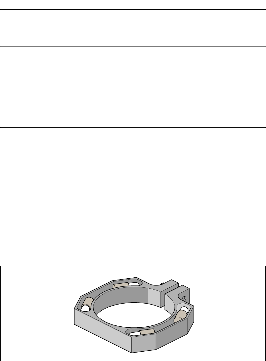
Fig. 5.5 - 3 Oblique lighting unit for the sub-gantry camera with ‘normal light’
Substrate format 50 mm x 50 mm to 100 mm x 180 mm
Substrate thickness 0.5 mm to 1.5 mm
Substrate model unscribed (without problems)
scribed (requires testing)
Support on the conveyor 2.5 mm
Optical centering: field of view of the PCB vision module
Type of illumination for light pastes:
Type of illumination for dark pastes and close spacing to
adjacent structures (> 1 mm)
5.7 mm x 5.7 mm
PCB vision module (standard)
Oblique lighting (option)
Fiducial criteria See PCB vision module position recog-
nition
Mechanical centering:
X/Y centering accuracy ± 0.07 mm / 4 sigma
PCB underside clearance 12 mm
Compressed air connection 5.5 bar
5 Station extensions User Manual SIPLACE S-25 HM
5.5 Ceramic substrate centering Software Version SR.503.xx 04/2002 US Edition
184
This oblique lighting unit may be switched on instead of the existing lighting (see table in section
5.5.2, page180).
PLEASE NOTE
Oblique lighting can only be used on the “sub-gantry camera”. 5
5.5.5.3 Oblique lighting unit with ‘blue light’ for fiducial recognition on ceramic or CEM
The ‘blue light’ oblique lighting unit often greatly improves the contrast between bright fiducials
on a light base material, such as ceramic or CEM (C
omposite Electrochemical Materials). Fidu-
cials covered with solder resist also stand out better from a light background.
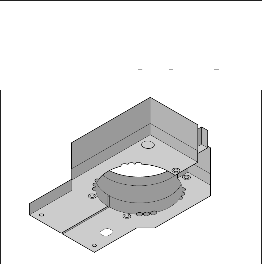
Fig. 5.5 - 4 Oblique lighting unit – blue light or IR light