00193463-01 - 第186页
5 Station extensions User Manual SIPLACE S-25 H M 5.5 Ceramic substrate centering Software Vers ion SR.503.xx 04/2002 US Edition 186 Fiducial s tructure 5 Recommenda tion 1 Fiduci al structu re Black res istive paste as …
User Manual SIPLACE S-25 HM 5 Station extensions
Software Version SR.503.xx 04/2002 US Edition 5.5 Ceramic substrate centering
185
5.5.5.4 Oblique lighting unit with ‘IR light’ for fiducial recognition on flex PCBs
The use of infrared light for fiducial recognition is particularly useful for fiducials that are covered
with solder resist or for fiducials on flex materials. It is also sometimes possible to improve recog-
nition of silver/platinum fiducials on ceramic. This should be tested by carrying out a test center-
ing or placement run.
The ‘IR light’ oblique lighting module has the same mechanical structure as the ‘blue light’
oblique lighting unit. The only difference is that it has infrared LEDs.
5.5.5.5 Fiducial mark recommendation for ceramic substrates
The contrast between the carrier package material and the circuit-board conductor layer is gener-
ally very small with ceramic substrates. The fiducials must therefore be selected with regard to
certain criteria concerning the fiducial shape and structure. Recommended fiducial shapes and
structures are given below. 5
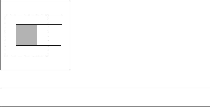
Fiducial shape 5
We recommend a rectangle or square with an edge length of > 1 mm, and a clearance
of > 0.5 mm. 5
5
Fig. 5.5 - 5 Recommended fiducial shape
PLEASE NOTE
Single crosses are also suitable, but they take up more space. 5
0.5 mm
1.0 mm

5 Station extensions User Manual SIPLACE S-25 HM
5.5 Ceramic substrate centering Software Version SR.503.xx 04/2002 US Edition
186
Fiducial structure 5
Recommendation 1
Fiducial structure Black resistive paste as the background, with conductive paste printed on it as
the fiducial.
Recommendation Background 0.75 mm larger than the fiducial on all sides.
Method of illumination Normal light
Advantage Good contrast, good sharpness;
Reference Circuit-board conductor layer
Assessment This combination gives the best results. Highly recommended.
Recommendation 2
Fiducial structure Fiducial made from circuit-board conductor material, e.g. 6119, and overprinted
with passivated glass 4330.
Method of illumination Oblique light
Advantage No additional steps required
Reference Circuit-board conductor layer
Assessment Fiducials are less sharp than for recommendation 1. Recommended.
Recommendation 3
Fiducial structure Fiducials made from circuit-board conductor layer against a free ceramic back-
ground.
Method of illumination Oblique or normal light (depending on the paste)
Advantage No additional steps required
Reference Circuit-board conductor layer
Note Fiducials are less sharp than for recommendation 2.
The fiducial image depends on the surrounding free surface. It may be neces-
sary to teach every circuit separately.
Assessment Recommended under certain conditions.
User Manual SIPLACE S-25 HM 5 Station extensions
Software Version SR.503.xx 04/2002 US Edition 5.6 PCB data transfer
187
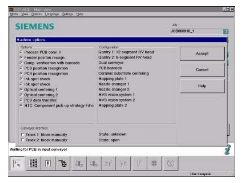
5.6 PCB data transfer
5.6.1 Functional description
The ’Machine options’ menu contains a ’PCB data transfer’ option. The aim of this function is to
increase the placement system’s performance on the line. To do this, an entire PCB is measured
at the first placement station and the associated fiducial, single circuit, ink spot, etc. data is deter-
mined, saved and sent to the next station. At subsequent stations, the data is then determined for
two fiducial positions only. These two fiducial positions are then used to correct the position for the
PCB to be processed at each station. It is thus not necessary to measure the entire PCB again,
together with its single circuits, ink spots etc. 5
5.6.2 Activating the ’PCB data transfer’ option
Fig. 5.6 - 1 Machine option: PCB data transfer