00193463-01 - 第19页
User Manual SIPLACE S-25 HM 1 Introduction, technical data Software Version SR.503.xx 04/2002 US Edition 1.4 Revision index 19 1.4 Revis ion inde x 1 1.4. 1 Revisi ons sinc e 01/2 001 edi tion 1 1 Manual Software version…

1 Introduction, technical data User Manual SIPLACE S-25 HM
1.3 User classification Software Version SR.503.xx 04/2002 US Edition
18
1.3 User classification
The operating software is structured so that certain functions or menus can only by used or called
by appropriately trained personnel. There are three different classes of user: 1
– operators,
– line engineers and
– service engineers.
Access to each class may be password-protected. Chapters containing information for user
classes higher than "operator" contain a reference to the user class concerned in the footer. 1
Operators 1
The operator class consists of any person who has been trained in operation of the machine.
These people are authorized to use any functions associated with operating the machine and may
call up any menus needed to use the machine. 1
Line engineers 1
Line engineers have undergone special training and are authorized to carry out line engineer ac-
tivities, such as creating set-up configurations, determining vision parameters, etc. 1
Service engineers 1
This class is intended for engineers from SIEMENSDEMATIC AG, who are trained to carry out ser-
vicing work and to upgrade and retrofit the placement system. 1
WARNING A thorough knowledge of the relevant part of this User Manual is re-
quired before carrying out any work on the machine. All work must be carried out by appropriately
trained and qualified personnel. All warning, caution and danger notes MUST be observed. 1
PLEASE NOTE: The content of this User Manual is not part of or intended to modify a previous or
existing agreement, undertaking or legal relationship. Any undertakings entered into by SIE-
MENSDEMATIC AG result from the purchase contract, which also contains complete and gener-
ally applicable guarantees. Such contractual guarantee provisions are neither extended nor
restricted by the information given in this User Manual. 1

User Manual SIPLACE S-25 HM 1 Introduction, technical data
Software Version SR.503.xx 04/2002 US Edition 1.4 Revision index
19
1.4 Revision index
1
1.4.1 Revisions since 01/2001 edition
1
1
Manual Software version Edition
First version User Manual SR.502.xx 11/2000 US
First edition User Manual SR.502.xx 01/2001 US
Revision of User Manual SR.503.xx 04/2002 US
New or modified Chapter / Section
Technical data - machine overview 1.5.3 on page 22
Electrical and pneumatic connection points 1.7 on page 24
Technical data – compressed air supply 1.8.2 on page 26
Dimensions and weight of the placement system 1.9 on page 27
Overview of the modules - vision modules 1.14 on page 44
Overview of the modules - PCB conveyor 1.15 on page 47
Safety instructions 2.1 on page 51
Disabling the compressed air supply and discharging the pressure 2.4 on page 90
Switching on the SIPLACE line 3.1 on page 102
Switching off the SIPLACE line 3.2 on page 107
Component table, mobile 3.8 on page 117
Surftape feeder 4.2.11 on page 139
Component table, mobile 4.6 on page 147
Dual conveyor 5.3 on page 170
Optical centering with oblique lighting 5.5.5 on page 183
Fine calibration 5.8 on page 190
DCA vision module on the 12-segment Collect&Place head 5.11 on page 202
DCA vision module on the 6-segment Collect&Place head 5.12 on page 205
Component sensor 5.13 on page 207
1 Introduction, technical data User Manual SIPLACE S-25 HM
1.5 Description of the machine Software Version SR.503.xx 04/2002 US Edition
20
1.5 Description of the machine
1.5.1 Functional description
The automatic placement system is a high-performance placement system with two gantries. A
PCB vision module and a 6 or 12-segment Collect&Place-head are mounted on each gantry. Col-
lect&place heads equipped with a component vision module pick up the components (CO) from
stationary feeder modules and place them onto the PCB clamped in the PCB conveyor. 1
1
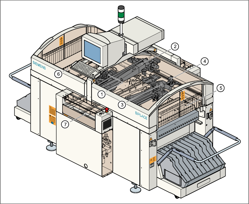
Fig. 1.5 - 1 Overall view of the placement system
(1) 6/12-segment Collect&Place head with component vision module (gantry 1)
(2) Gantry 1 with PCB vision module
(3) 6/12-segment Collect&Place head with component vision module (gantry 2)
(4) Gantry 2 with PCB vision module
(5) Stationary component supply (location 1)
(6) Stationary component supply (location 3)
(7) PCB conveyor (dual conveyor option)