00193463-01 - 第190页
5 Station extensions User Manual SIPLACE S-25 H M 5.8 Fine calibration Software Vers ion SR.503.xx 04/2002 US E dition 190 5.8 Fine calibrati on 5.8.1 Overvie w Fine ca librati on invol ves meas uring th e mach ine’s pla…
User Manual SIPLACE S-25 HM 5 Station extensions
Software Version SR.503.xx 04/2002 US Edition 5.7 Feeder position recognition
189
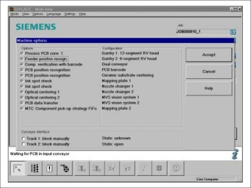
5.7 Feeder position recognition
If the feeders are equipped with positioning fiducials, the fiducials can be measured.
If the "Conveyor position detection" function has been selected on the line computer, the function
will also appear in the Machine options. It can then be activated or deactivated at each station.
Fig. 5.7 - 1 Feeder position recognition
5
If a track has been entered in the cluster data, the PCB camera on the feeder will approach the
position of the centering fiducial. Any centering fiducial offset determined during the measurement
will then be assigned to this track and added to the pick-up position during the pick-up operation. 5

5 Station extensions User Manual SIPLACE S-25 HM
5.8 Fine calibration Software Version SR.503.xx 04/2002 US Edition
190
5.8 Fine calibration
5.8.1 Overview
Fine calibration involves measuring the machine’s placement offset and determining the required
correction from this value. The ‘Fine calibration’ measuring program is integrated into the SIT-
EST program, and a detailed description of the measuring procedure is given in the ‘Fine calibra-
tion’ instructions (article no. 00191655-01).
CAUTION
The SITEST program is password-protected. It must only be called up and used by SiemensDe-
matic engineers or appropriately trained personnel. 5
5.8.2 System requirements
The following system requirements must be fulfilled in order to use the fine calibration program:
Machine type S-25 HM
Station computer software version 503.xx or later
SITEST version 503.xx or later
PLEASE NOTE: 5
The fine calibration can only be carried out with the 12-segment Collect&Place head. 5
5.8.3 Measuring equipment and tools
The following are supplied as standard:
– Mapping plate (glass plate in a metal frame)
– Double-sided transparent adhesive film
– Lighting unit
– CERAM components in the feeder for the 12-segment Collect&Place head
User Manual SIPLACE S-25 HM 5 Station extensions
Software Version SR.503.xx 04/2002 US Edition 5.8 Fine calibration
191
5.8.4 Functional description
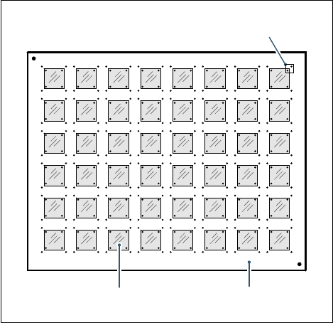
A large number of CERAM components are placed on a glass PCB covered with adhesive film.
On the top of the CERAM components there are reference fiducials in each corner. The glass
PCB also has reference fiducials in the immediate vicinity of these component fiducials.
. 5
Fig. 5.8 - 1 Fine calibration principle
Immediately after placement, the PCB camera takes four sets of images of the associated refer-
ence fiducials on both PCB and component. The analysis program is then used to determine the
placement offset in the X/Y direction and the angular deviation
Φ. The offset values are used to
calculate the corrected values, which are then entered in the machine data (FK_off.ma).
5.8.5 Measuring modes
The following measurement modes can be selected:
– Measure the values for an individual placement head.
– Measure the values for all the placement heads in a placement area.
– Measure the values for the entire machine.
The measurement can be repeated as often as required, with or without replacing the CERAM
components.
Field of view of the PCB camera
Glass components Glass PCB