00193463-01 - 第202页
5 Station extensions User Manual SIPLACE S-25 H M 5.11 DCA v ision module on th e 12-segment C ollect&Place head S oftware Vers ion SR.503.xx 04/2002 US E dition 202 5.1 1 DCA vision module on the 12-segment Collect&…
User Manual SIPLACE S-25 HM 5 Station extensions
Software Version SR.503.xx 04/2002 US Edition 5.10 Vacuum tooling
201
5.10 Vacuum tooling
Vacuum tooling is another module that is used to increase the placement accuracy for concave
PCBs. The vacuum surface of this device picks up concave PCBs during processing and aligns
them so they are flat. 5
The vacuum tooling module can be used on both single and dual conveyors, and is fitted to the
lifting tables. 5
Description of the functions 5
The PCB is fed to the processing belt, where it is stopped. The lifting table moves up and the vac-
uum circuit for the vacuum tooling device is opened. The PCB is then held in place by the vacuum
tooling device, which is pressed with a spring action against the PCB by the lifting table. This
causes the suction cups of the tooling device to press against the PCB and hold it firmly in posi-
tion. 5
The vacuum channels are vented after placement. The lifting table is lowered, the PCB is re-
leased, and can then be moved on. 5
5 Station extensions User Manual SIPLACE S-25 HM
5.11 DCA vision module on the 12-segment Collect&Place head Software Version SR.503.xx 04/2002 US Edition
202
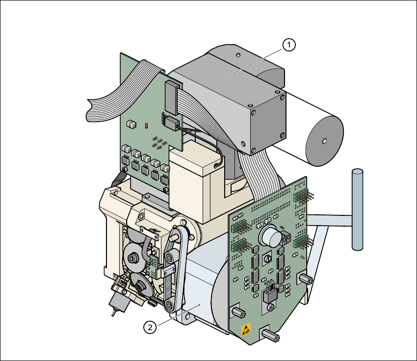
5.11 DCA vision module on the 12-segment
Collect&Place head
5
Fig. 5.11 - 1 DCA vision module on the 12-segment Collect&Place head
5
(1) DCA vision module
(2) 12-segment Collect&Place head

User Manual SIPLACE S-25 HM 5 Station extensions
Software Version SR.503.xx 04/2002 US Edition 5.11 DCA vision module on the 12-segment Collect&Place head
203
5.11.1 Description of the 12-segment Collect&Place head with
DCA vision module
With the DCA vision module, the 12-segment Collect&Place head is able to optically center and
place components of the order of magnitude of 0.6mm x 0.3mm to 13mm x 13mm. The DCA
package optimizes the speed and accuracy when placing high-speed flip chips and bare die
components.
5.11.2 Technical data for the 12-segment Collect&Place head with
DCA vision module
Component range 0201 to 13 mm x 13 mm
Component specification
Max. height
Min. lead pitch
Min. bump pitch
Min. ball/bump diameter
Min. dimensions
Max. dimensions
Max. weight
6 mm
0.4 mm
0.2 mm
0.11 mm
0.6 mm x 0.3 mm
13 mm x 13 mm
2 g
Travel of the Z axis Max. 16 mm
Programmable placement force 2.4 to 5.0 N
Nozzle types 9xx
Max. placement rate 12,500 components/hour
Angular accuracy ± 0.7° / 4
σ
Placement accuracy of the DCA vision
module
± 90 µm / 4
σ