00193463-01 - 第210页
5 Station extensions User Manual SIPLACE S-25 H M 5.14 SIPLACE productivity lift S oftware Version SR.503.xx 04/2002 US Edition 210 5.14 SIPLACE productivity lif t 5.14.1 Concept of p arallel plac ement Placeme nt lines …
User Manual SIPLACE S-25 HM 5 Station extensions
Software Version SR.503.xx 04/2002 US Edition 5.13 Component sensor
209
5.13.2 Measuring conditions
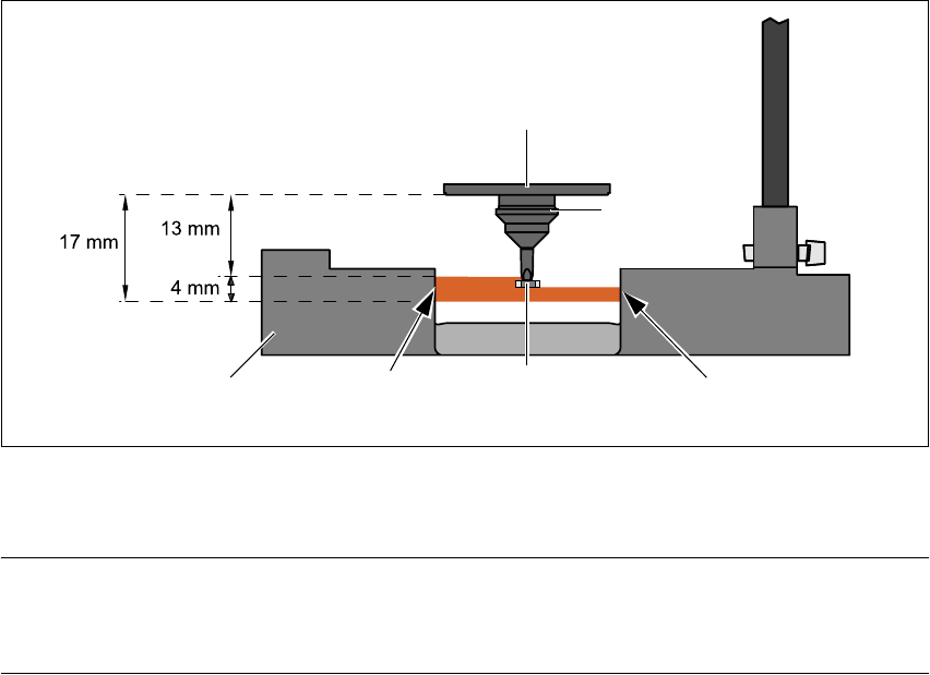
The following conditions must be fulfilled in order to obtain a valid measurement:
– The light beam must touch the empty nozzle tip during the calibration process.
– The nozzle tip must be inside the light beam when it is holding a component.
– Minimum nozzle length 13 mm
– Nozzle length + component height + tolerance < 17 mm
If these conditions are fulfilled, it is possible to determine whether a component is present or ab-
sent, or to measure the component height.
The minimum difference in height is 100 µm.
5
Fig. 5.13 - 3 Component sensor, working principle
5
5
PLEASE NOTE 5
If you are placing 0201 components with the 906 nozzle, it is essential to use the component sen-
sor since no vacuum measurements are possible. 5
Using the component sensor can also improve the dpm rate when placing other small compo-
nents, such as 0402 or 0603 components.
When selecting the component sensor from the package form list, note that the component can
only be placed on machines that are equipped with that component sensor.
Incremental disk
Component
Nozzle
IR LED PhototransistorCross-section
through component sensor
5 Station extensions User Manual SIPLACE S-25 HM
5.14 SIPLACE productivity lift Software Version SR.503.xx 04/2002 US Edition
210
5.14 SIPLACE productivity lift
5.14.1 Concept of parallel placement
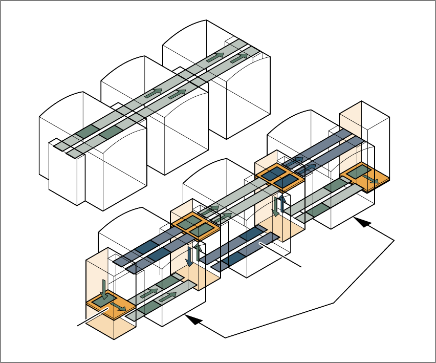
Placement lines are generally arranged in series and are linked to one another serially. The
placement program is processed sequentially while the PCBs are transported from one machine
to the next. This means that the placement of a PCB is distributed between various machines.
5
Fig. 5.14 - 1 A comparison of serial and parallel lines
When machines are connected in parallel, the components to be placed by individual machines
are combined, so several machines work through the same placement program. They place all
the components on one machine that would be distributed between several machines with serial
processing. When one machine runs out of capacity, the PCBs are moved to and placed at the
next machine with the same placement program. This combination of machines with the same
components to be placed is known as a group or “cluster”.
Serial line
Parallel line
Underfloor conveyor
Group (cluster)
Horizontal/
vertical lift
User Manual SIPLACE S-25 HM 5 Station extensions
Software Version SR.503.xx 04/2002 US Edition 5.14 SIPLACE productivity lift
211
5.14.2 Implementing parallel placement
Lines with machines arranged in parallel take up a lot more space, so the parallel placement con-
cept was implemented with an underfloor conveyor and horizontal / vertical lift (HV shuttle). The
machines are still arranged in series, but the lift units and underfloor conveyors allow the line to
be operated in parallel. In this way, SIPLACE lines remain almost as compact as before.
Underfloor conveyor
Two conveyor belts carry empty or placed PCBs underneath the machines (see Fig. 5.14 - 1).
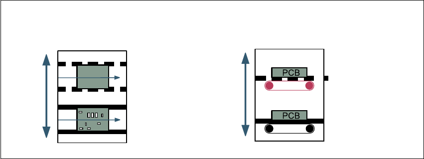
Horizontal/vertical lift (horizontal/vertical shuttle)
There is an HV shuttle at the start of a line, between the machines and at the end of the line. It
carries the PCBs between the underfloor and processing levels, and between the two tracks on
the underfloor conveyors.
5
Fig. 5.14 - 2 Horizontal / vertical shuttle (HV shuttle), conveyor track change and lift function
Horizontal conveyor
HV shuttle
Lift function
Vertical conveyor
Unplaced
Placed
Standard
conveyor level
Underfloor
conveyor level
HV shuttle
Conveyor track change