00193463-01 - 第47页
User Manual SIPLACE S-25 HM 1 Introduction, technical data Software Vers ion SR.503.xx 04/2002 US Edition 1.15 Overview of t he modules - P CB conv eyor 47 1.15 O verview of the modules - PCB convey or 1.15.1 Structure o…
1 Introduction, technical data User Manual SIPLACE S-25 HM
1.14 Overview of the modules - vision modules Software Version SR.503.xx 04/2002 US Edition
46
1.14.4 Technical data - component vision module (standard camera) on the
6-segment Collect&Place head
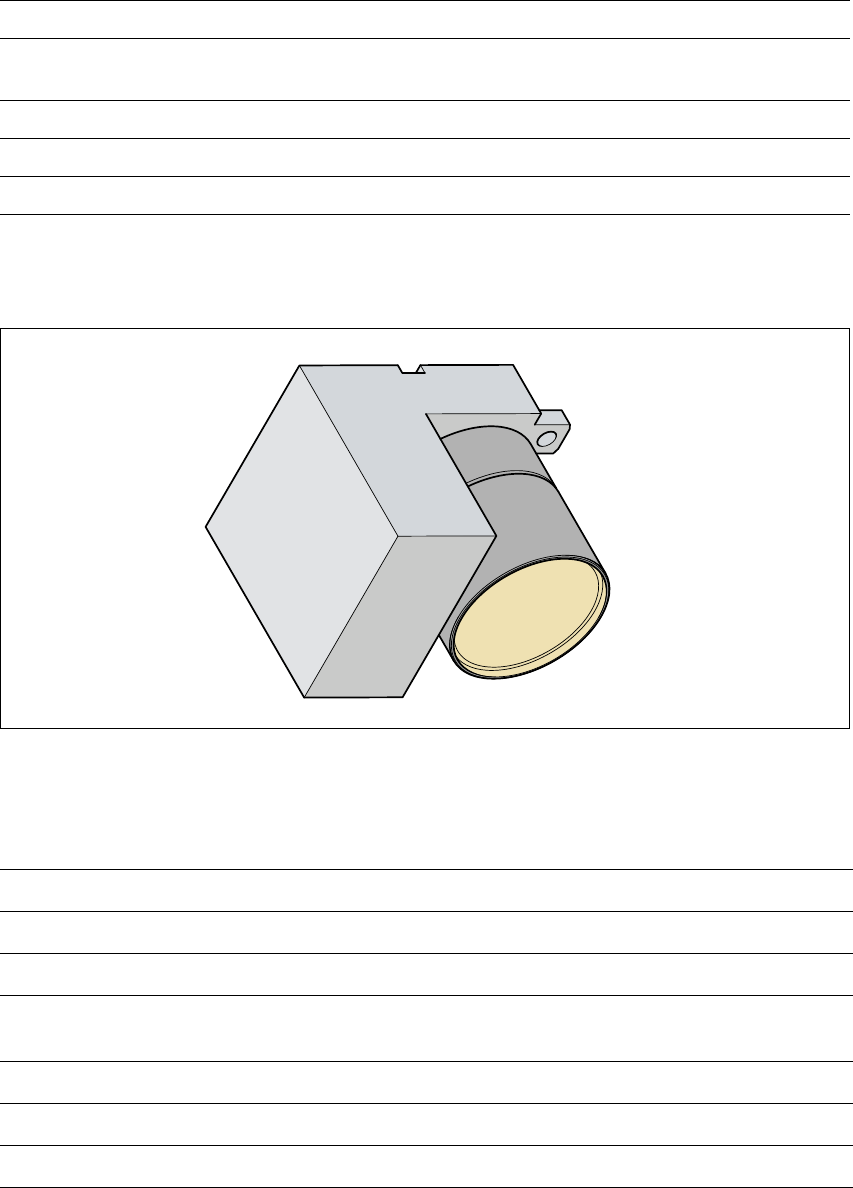
1.14.5 PCB vision module
1
Fig. 1.14 - 3 PCB vision module
1.14.6 Technical data - PCB vision module
1
Component dimensions 0.5mm x 1.0mm to 32mm x 32mm
Component range
0603 to 32mm x 32mm
PLCC, SO, QFP, TSDP, SOT, MELF, CHIP, IC BGA
Minimum lead pitch 0.5 mm
Field of view 24mm x 24mm
Method of illumination Front lighting (3 levels programmable as required)
Fiducials Up to 3 per placement program
Local fiducials Up to 2 per PCB (may be of different types)
Library size Up to 255 fiducial types - system fiducials
≥ 249
Image processing Correlation principle or contour following method
(geometric alignment)
Illumination method Front-lighting
Recognition time per fiducial/ink spot 0.4 s
Field of vision 5.7 mm x 5.7 mm
User Manual SIPLACE S-25 HM 1 Introduction, technical data
Software Version SR.503.xx 04/2002 US Edition 1.15 Overview of the modules - PCB conveyor
47
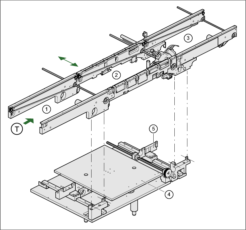
1.15 Overview of the modules - PCB conveyor
1.15.1 Structure of the PCB conveyor
The placement system is supplied with a single conveyor as standard. A dual conveyor is avail-
able as an option. 1
The left or the right side of the PCB conveyor can be used as the stationary side, as required. 1
1
Fig. 1.15 - 1 PCB transport - single conveyor
(1) Input conveyor (2) Center conveyor
(3) Output conveyor (4) Lifting table
(5) Width adjustment T Direction of PCB transport 1

1 Introduction, technical data User Manual SIPLACE S-25 HM
1.15 Overview of the modules - PCB conveyor Software Version SR.503.xx 04/2002 US Edition
48
The conveyor belts are driven by DC motors. The lifting table near the center conveyor clamps the
PCBs in position. The width of the PCB conveyor can be adjusted either 1
– via the menu or
– using the line computer.
1
1.15.2 Technical data – single conveyor system
1
1
1
1
1.15.3 Technical data – dual conveyor system
1
PCB format
(length x width)
50 mm x 50 mm to 508 mm x 460 mm
(2" x 2" to 20" x 18")
Long-board option: length up to 610 mm (24")
PCB thickness 0.5mm to 4.5mm
Max. PCB warpage On top: 4.5mm - PCB thickness
On bottom: 0.5mm + PCB thickness
Clearance on PCB underside 25mm (standard), 40mm (option)
PCB transport height 830mm ± 15mm (standard)
900mm ± 15mm (option)
930mm ± 15mm (option)
950mm ± 15mm (SMEMA: optional)
Fixed conveyor edge Right (standard), left (optional)
Type of interface Siemens (standard),
SMEMA (option)
Component-free handling edge 3mm
PCB changeover time 2.5 s
Bad fiducial recognition possible
Automatic width adjustment possible
PCB format
(length x width)
50 mm x 50 mm to 508 mm x 216 mm
(2" x 2" to 20" x 8.5")
Long-board option: length up to 610 mm (24")
PCB thickness 0.5mm to 4.5mm
Max. PCB warpage On top: 4.5mm - PCB thickness
On bottom: 0.5mm + PCB thickness