00193463-01 - 第90页
2 Operational Safety User Manual S IPLACE S-25 H M 2.4 Disabling the compressed air supply and discharging the pressure Software Version SR.503.xx 04/2002 US Edition 90 2.4 Disabling the compresse d air supply and di sch…

User Manual SIPLACE S-25 HM 2 Operational Safety
Software Version SR.503.xx 04/2002 US Edition 2.3 Residual voltages in the servo unit and discharge times
89
2.3.1 Operating voltages, residual voltages and discharge times after pressing
the emergency stop mushroom-head push-button
2
2.3.2 Residual voltages and discharge times after switching off at the main switch
2
CAUTION To avoid losing data, evaluate the following criteria before switching off your
automatic placement system (apart from in emergencies):
– Has the placement system finished transmitting machine, set-up and working data?
– Has the placement system finished processing the PCB?
– Has the placement system completed the run-up phase?
– Has the Windows NT operating system been shut down correctly? 2
Test socket 00X
measured at 007
(GND)
Voltage
in normal mode
Residual voltage
after emerg. stop
Discharge times
of electrolytic
capacitors at 12 VDC
001 70 VDC 10 VDC < 2 sec
002 30 VDC 30 VDC –
003 30 VDC < 12 VDC < 2 sec
004 24 VDC 24 VDC –
005 12 VDC 12 VDC –
006 5 VDC 5 VDC –
008 70 VDC 10 VDC < 2 sec
009 155 VDC 10 VDC < 1 sec
Tab. 2.3 - 1 Operating voltages, residual voltages and discharge times after pressing the emergency stop
mushroom-head push-button
Test socket 00X
measured at 007 (GND)
Residual voltage
when main switch is off
Discharge times of electrolytic
capacitors at 12 VDC
001 < 12 VDC < 2 sec
002 < 12 VDC < 2 sec
003 < 12 VDC < 2 sec
004 0 VDC –
005 0 VDC –
006 0 VDC –
008 < 12 VDC < 2 sec
009 < 12 VDC < 1 sec
Tab. 2.3 - 2 Residual voltages and discharge times after switching off at the main switch
2 Operational Safety User Manual SIPLACE S-25 HM
2.4 Disabling the compressed air supply and discharging the pressure Software Version SR.503.xx 04/2002 US Edition
90
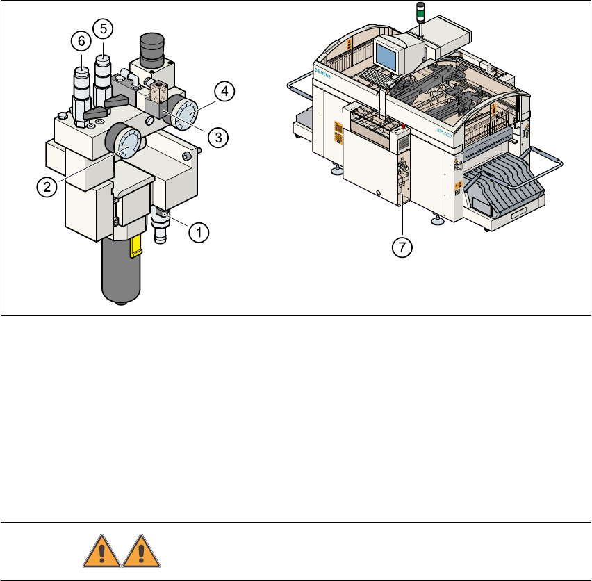
2.4 Disabling the compressed air supply and discharg-
ing the pressure
The compressed air working pressure is set to 5.1 bar, although it may fluctuate between 5.0 and
5.3 bar. The position of the compressed air unit is indicated by item 5 in Fig. 2.4 - 1. The com-
pressed air supply to the machine can be interrupted using the shut-off valve (item 1 in
Fig. 2.4 - 1). 2
– You must remove the cover plate to use the shut-off valve.
– Turn the lever on the shut-off valve (item 1 in Fig. 2.4 - 1) from the vertical to the horizontal
position.
– Watch the working pressure gauge (item 2 in Fig. 2.4 - 1) and the pressure gauge for the com-
pressed air supply to the stopper (item 4 in Fig. 2.4 - 1). When the automatic placement system
is switched on, the pressure discharges to 0 bar within 1 minute.
Fig. 2.4 - 1 Compressed air unit on the automatic placement system
WARNING Never disconnect compressed air lines while they are pressurized. 2
(1) Shut-off valve lever in the CLOSED position
(2) Working pressure gauge
(3) Solenoid valve for venting the tape cutter during an emergency stop
(4) Pressure gauge for the PCB stopper working pressure
(5) Compressed air supply, gantry 2
(6) Compressed air supply, gantry 1
(7) Position of the compressed air unit
User Manual SIPLACE S-25 HM 2 Operational Safety
Software Version SR.503.xx 04/2002 US Edition 2.5 Energy state of the machine after switching off at the main switch
91
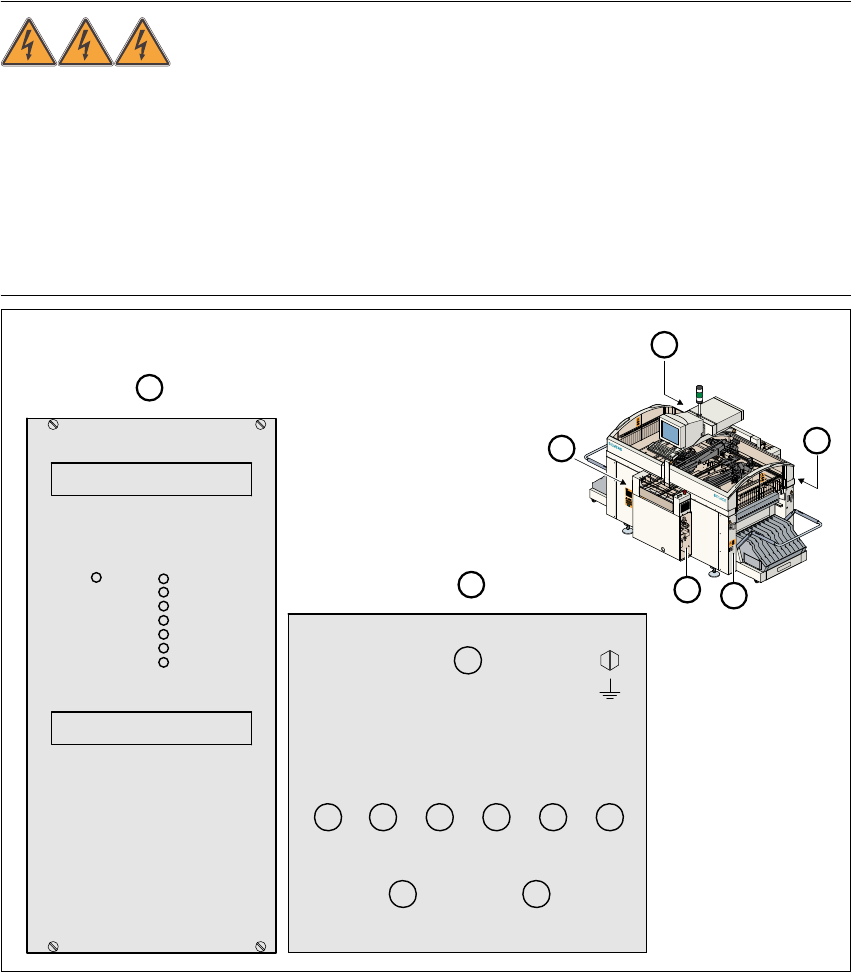
2.5 Energy state of the machine after switching off at
the main switch
DANGER
Automatic placement systems from the SIPLACE family are powered with 3 x 400 V or 3 x
208 VAC (U.S.A. version) ± 5 %, 50/60 Hz mains voltage. This means that parts of the system
carry potentially fatal voltages - even when switched off at the main switch. Death, serious injury
or considerable damage may result if these placement systems are handled incorrectly.
Always follow the applicable accident prevention and DIN regulations (particularly EN 60204,
part 1). The guards over the control and servo units must ONLY be opened by appropriately qual-
ified and trained personnel. 2
Fig. 2.5 - 1 Position of the control unit, servo unit, main switch, service socket and compr. air unit
1 Main switch Q1 2 Compressed air unit
3 Service socket 4 Servo unit
5 Control unit 6 Power supply for control unit
7 Measuring unit, servo unit
GND
007
001 002 003 004 005 006
008 009
70VDC/
10VDC
30VDC 24VDC 12VDC 5VDC
70VDC
155VDC/0VDC
30VDC
7
6
4
2
3
1
5
GND
+24V
-15V
+15V
-12V
+12V
+5V
Fail
un-
switched
switched