ACT - Accuracy Check Tool mit SSW 6xx User Manual 2017.pdf - 第114页
ACT with SSW 6xx / User Manual 07/2017 Edition 50 Figure 4-27: Dialog box after AC T mode has been set. Displ ay: ACT icon The Leiterpl atteneingabe (Enter PCB) dialog b ox opens ( Figure 4 - 28 ): ► Select the ACT boar …
ACT with SSW 6xx / User Manual 07/2017 Edition
49
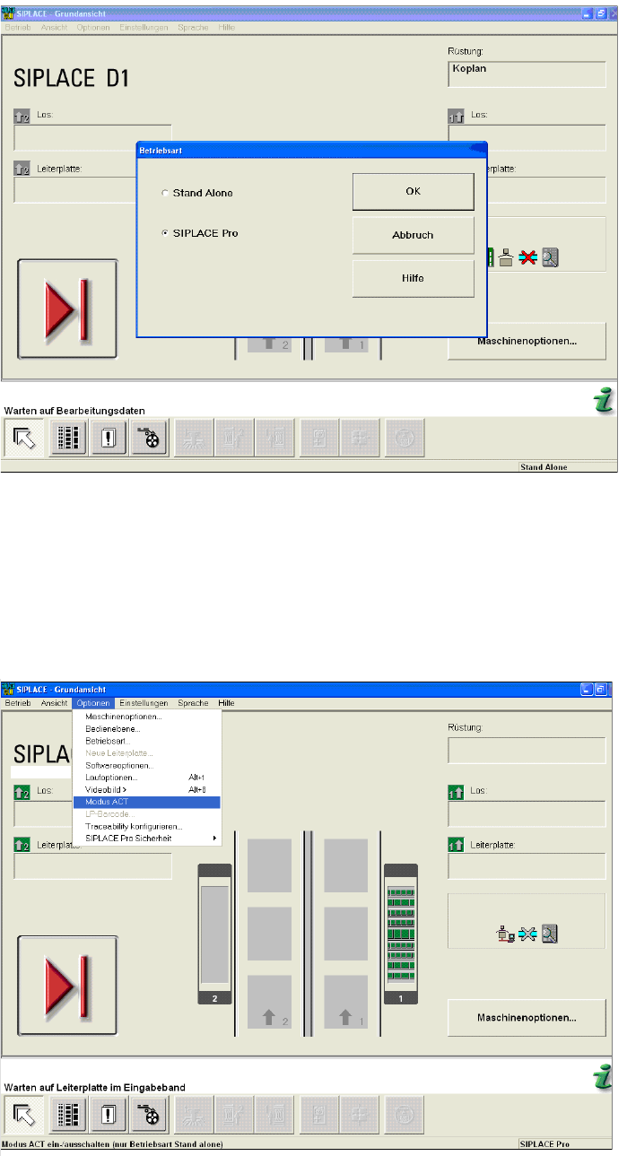
Figure 4-25: Dialog box operating mode switchover to SIPLACE Pro at the station (example SIPLACE D1)
► Press the START button on the machine.
The reference run is executed.
► Send the recipe / job to the station with the relevant setup and the ACT placement program.
► From the Optionen (Options) menu, select Modus ACT (ACT mode).
The ACT dialog box opens and the machine will automatically switch to Stand Alone mode.
Figure 4-26: Basic view of user interface for SC program (example SIPLACE D1)
After setting Modus ACT (ACT mode) an icon is displayed for ACT.
ACT with SSW 6xx / User Manual 07/2017 Edition
50
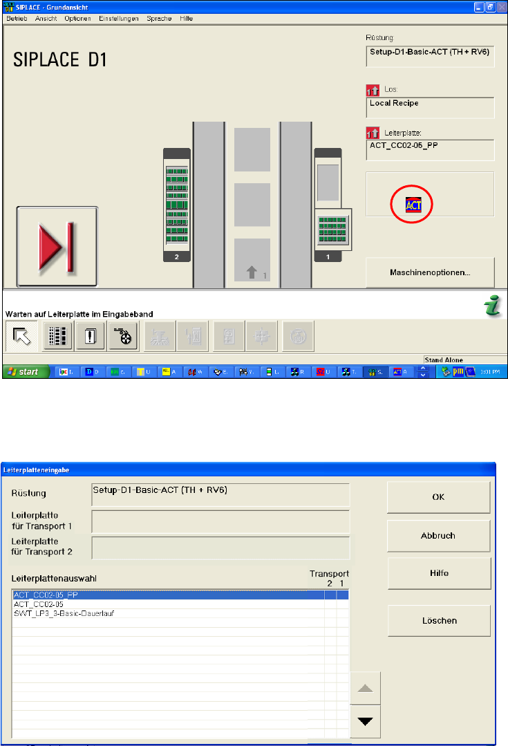
Figure 4-27: Dialog box after ACT mode has been set. Display: ACT icon
The Leiterplatteneingabe (Enter PCB) dialog box opens (Figure 4-28):
► Select the ACT board.
Figure 4-28: Dialog box: Enter PCB (example SIPLACE D1)
The Leiterplatteneingabe (Enter PCB) dialog box opens (Figure 4-29):
► Select the ACT board.
► Select the conveyor lane.
► Confirm your entry with OK.
ACT with SSW 6xx / User Manual 07/2017 Edition
51
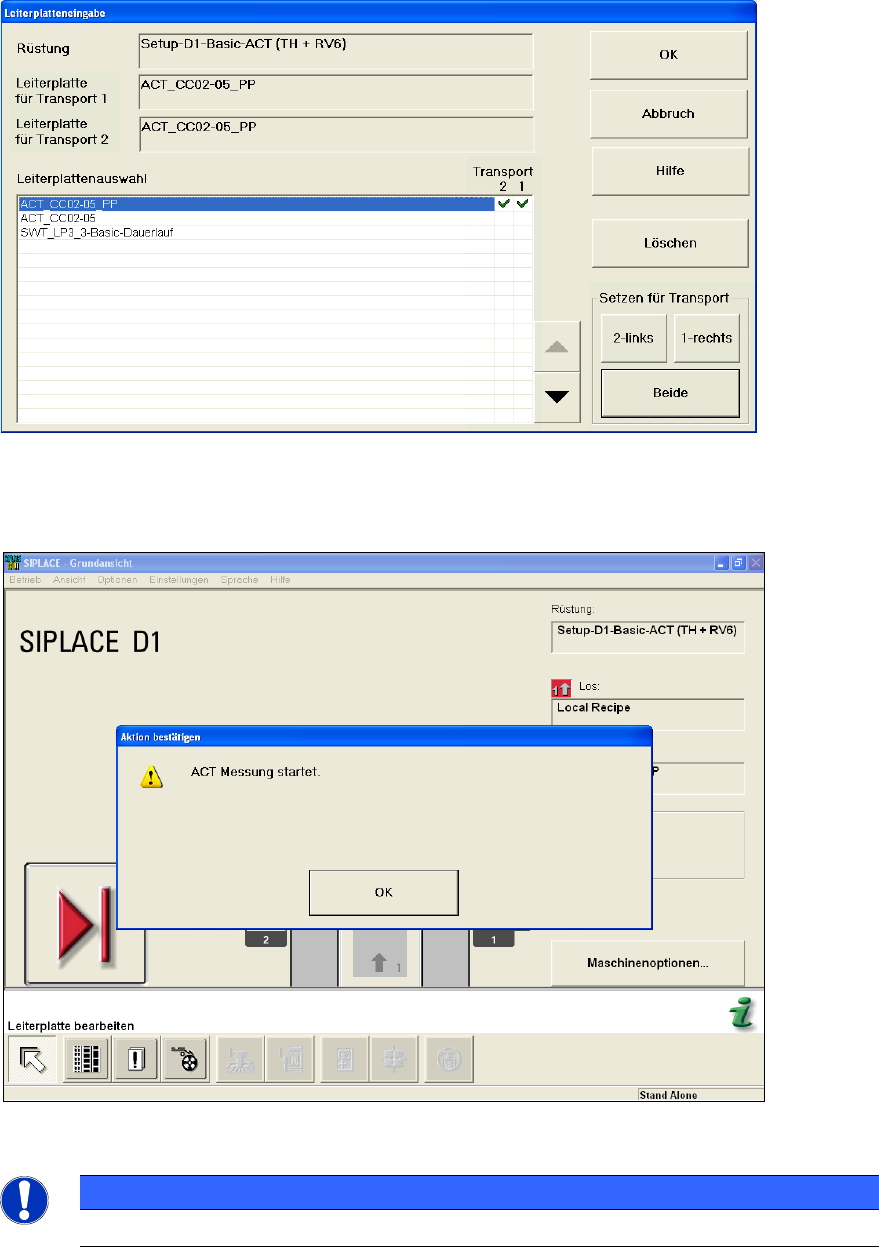
Figure 4-29: Dialog box: Enter PCB (example SIPLACE D1)
► Push the board into the input section (see also section 4.2.2).
The board gets placed and then the measurement starts automatically.
Figure 4-30: Message for ACT measurement (example SIPLACE D1)
NOTICE
The machine should not be operated during the measurement!
A dialog box opens in which the current measurement operation is displayed. The fiducials which
are currently being measured will be displayed.