00198271-02_UM_ShuttleExtensionTX_EN.pdf - 第42页
3 Assembly Instruct ion Assembly and User Manual 3.3 Installation Shuttle Extension Edition 06/2017 40 General 3 Remove th e four side covers fr om the Shuttle Extension. This gi ves you access to the fixtures for the …
Assembly and User Manual 3 Assembly Instruction
Shuttle Extension Edition 06/2017 3.3 Installation
39
3.3.2 Mechanical Installation Procedure
Intermediate ledges on SIPLACE TX output conveyor side 3
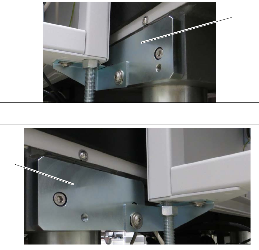
Fit the two intermediate ledges to the machine feet of the SIPLACE TX output conveyor side.
Fig. 3.3 - 3 Intermediate ledge - right side
Fig. 3.3 - 4 Intermediate ledges -left side
(1) Intermediate ledge input conveyor - right side
(2) Intermediate ledge input conveyor - left side
(1)
(2)
3 Assembly Instruction Assembly and User Manual
3.3 Installation Shuttle Extension Edition 06/2017
40
General 3
Remove the four side covers from the Shuttle Extension. This gives you access to the fixtures
for the interface brackets and the electrical connection.
Move the Shuttle Extension to the SIPLACE TX.
Set the height of the Shuttle Extension, so that the PCB conveyor for the Shuttle Extension
is the same height as the PCB conveyor for the SIPLACE TX.
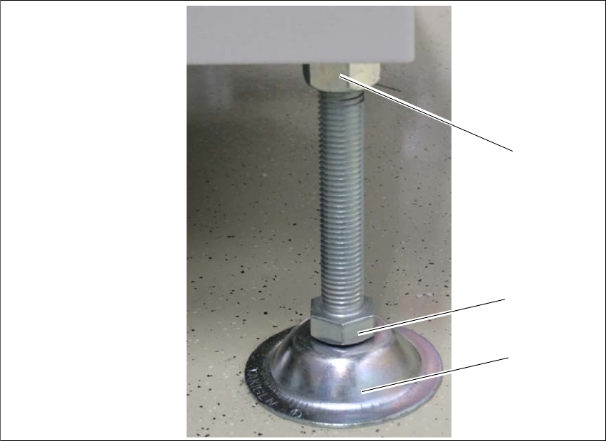
The Shuttle Extension stands on 4 feet.
Fig. 3.3 - 5 Presetting the height of the machine feet
(1) Top screw nut
(2) Bottom screw nut
(3) Shuttle Extensions feet
Turn the Shuttle Extension feet (3) with the bottom screw nut (2) so that the Shuttle Extension
has the PCB conveyor height of the SIPLACE TX.
Tighten the top screw nut (1), so that the machine feet are fixed into place.
Check the height of the Shuttle Extension and correct the height, if necessary.
(1)
(2)
(3)
Assembly and User Manual 3 Assembly Instruction
Shuttle Extension Edition 06/2017 3.3 Installation
41
Adjustment 3
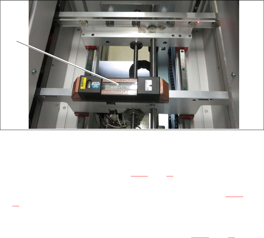
Place a machine spirit level (measuring accuracy of 0.02 mm) against the edge of the Shuttle
Extension PCB conveyor.
Fig. 3.3 - 6 Machine spirit level measuring accuracy of 0.02 mm) on conveyor rail
Use the machine spirit level (1) to align the Shuttle Extension in the X and Y direction, at the
four machine feet.
Loosen the top screw nut (item 1 in see fig. 3.3 - 5, page 40) with the help of a s open-ended
wrench.
Use the open-ended wrench to adjust the buttom screw nut (item 2 in see fig. 3.3 - 5, page
40
) of all four Shuttle Extension feet, so that the fluid in the machine spirit level does not de
-
viate from its zero point at the required conveyor height.
Check the required board conveyor height.
Use the torque wrench to tighten top screw nut (item 1 in see fig. 3.3 - 5, page 40) to clamp
all Shuttle Extension feet.
(1)