00198271-02_UM_ShuttleExtensionTX_EN.pdf - 第47页
Assembly and User Manual 3 Assembly Instruction Shuttle Extension Edition 06/2017 3.3 Installation 45 Finalize 3 Leave a ga p of 2 m m to 8 mm between th e frame of the SIPLACE TX and the fram e of the Shuttle Extensio…
3 Assembly Instruction Assembly and User Manual
3.3 Installation Shuttle Extension Edition 06/2017
44
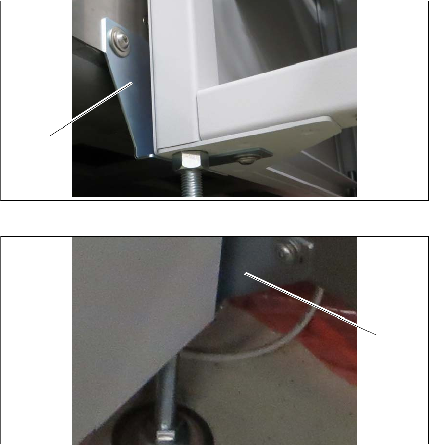
Interface brackets on output Shuttle Extension side 3
Fig. 3.3 - 11 Interface brackets on output conveyor - left side
Fig. 3.3 - 12 Interface brackets on output conveyor - right side
(1) Interface bracket output conveyor - left side
(2) Interface bracket output conveyor - right side
(1)
(2)

Assembly and User Manual 3 Assembly Instruction
Shuttle Extension Edition 06/2017 3.3 Installation
45
Finalize 3
Leave a gap of 2 mm to 8 mm between the frame of the SIPLACE TX and the frame of the
Shuttle Extension. See fig. 3.3 - 1
, page 38.
Check the transition between the Shuttle Extension and the SIPLACE TX again.
If necessary, correct the height at the feet or the fixture of the interface brackets.
Once the Shuttle Extension has been finally aligned, use the torque wrench to tighten top
screw nut (item 1 in see fig. 3.3 - 5
, page 40) to clamp all Shuttle Extension feet.
3 Assembly Instruction Assembly and User Manual
3.4 Electrical Connections Shuttle Extension Edition 06/2017
46
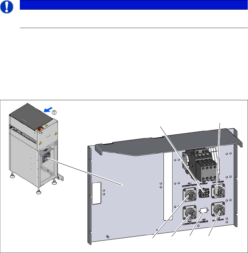
3.4 Electrical Connections
3
3.4.1 Shuttle Extension
Connect the following cables to the Shuttle Extension connection.
– 4 x SMEMA Cable [Item. No.: 03152800-xx]
– 1 x CAN Bus cable [Item. No.: 03133551-xx]
– 1 x Power interface cable to SIPLACE TX [Item. No. 03133550-xx]
Fig. 3.4 - 1 Electrical connection on the Shuttle Extension
(1) SMEMA connection XL1 UPSTREAM - Lane 1 to predecessor machine
(2) SMEMA connection XL2 UPSTREAM - Lane 2 to predecessor machine
(3) CAN-BUS connection
(4) SMEMA connection XL2 DOWMSTREAM - Lane 2 to successor machine
(5) SMEMA connection XL1 DOWMSTREAM - Lane 1 to successor machine
(6) POWER interface X50 to SIPLACE TX
PLEASE NOTE
Use of the circuit diagrams of the Shuttle Extension
For detail information, please refer to the circuit diagrams of the Shuttle Extension.
(6)
(1)
(2)
(3)
(4)
(5)