00198271-02_UM_ShuttleExtensionTX_EN.pdf - 第57页
Assembly and User Manual 4 Calibration Shuttle Extension Edition 06/2017 4.2 Perform Calibration 55 Fig. 4.2 - 2 Station Software - ""Single calibrat ion" view Click the Shuttle calibration icon (1 or 2)…
4 Calibration Assembly and User Manual
4.2 Perform Calibration Shuttle Extension Edition 06/2017
54
4.2 Perform Calibration
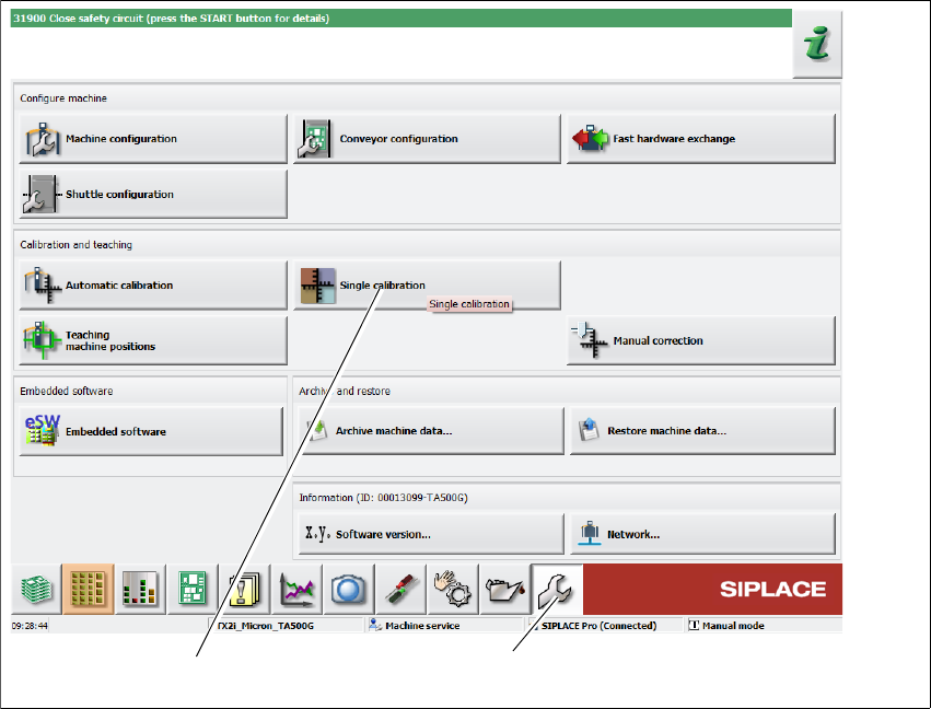
Click Service (1) icon from the station GUI tool bar.
Fig. 4.2 - 1 Station Software - "Service" view
Click Single calibration icon (2).
(1)
(2)
Assembly and User Manual 4 Calibration
Shuttle Extension Edition 06/2017 4.2 Perform Calibration
55
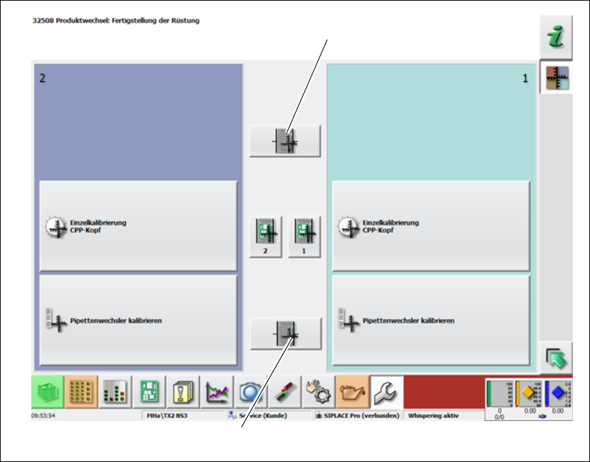
Fig. 4.2 - 2 Station Software - ""Single calibration" view
Click the Shuttle calibration icon (1 or 2).
– Shuttle on output conveyor icon 1
– Shuttle on input conveyor icon 2
(2)
(1)
4 Calibration Assembly and User Manual
4.2 Perform Calibration Shuttle Extension Edition 06/2017
56
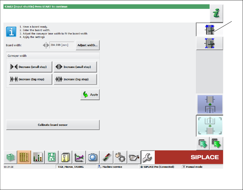
Step 1: Calibrating the width 4
To ensure that the board can be taken accurately from the previous machine and transported to
the next machine, the conveyor for the Shuttle Extension must be exactly configured to the width
of the board. Make sure that the board can be moved freely but does not have too much play.
Fig. 4.2 - 3 Station Software - "Width Calibration" view
Click Width Calibration icon (1).
Get a board ready.
Select the Adjust width... button, specify the width of the board present and select the Start
button.
Place a board in the Shuttle Extension and use the Decrease / Increase buttons to set the
width so that the board can be freely moved in the conveyor.
Select the Apply button.
Optional: How to calibrate the board sensor
Make sure that there is no board left in the Shuttle Extension.
Select the Calibrate board sensor button.
(1)