00198271-02_UM_ShuttleExtensionTX_EN.pdf - 第8页
1 Introduction Assembly and User Manual SIPLACE TX 1.1 Description Shuttle Extension Edition 06/2017 6 As an exam ple, the fo llowi ng scenarios are possible: – SIPLACE TX with dual conve yor (I -P lacement) on a SIPLACE…
Assembly and User Manual 1 Introduction
Shuttle Extension Edition 06/2017 1.1 Description
5
1 Introduction
This manual is a guide or reference work for installation, operating and setting up the SIPLACE
®
Shuttle Extension.
1.1 Description
The Shuttle Extension TX enables you to connect a SIPLACE TX placement machine to another
machine (e.g. SIPLACE SX, printer, furnace) with a different conveyor mode. The Shuttle
Extension TX balances the positions of the fixed rail in the various conveyor modes (I-Placement
to alternating) and regulates the lane accuracy during transportation of the boards. It is also pos
-
sible to connect a dual conveyor to a single conveyor and vice versa. Furthermore, you can con
-
nect an additional processing device (such as a printer or furnace) which has a different conveyor
mode to that of the SIPLACE TX.
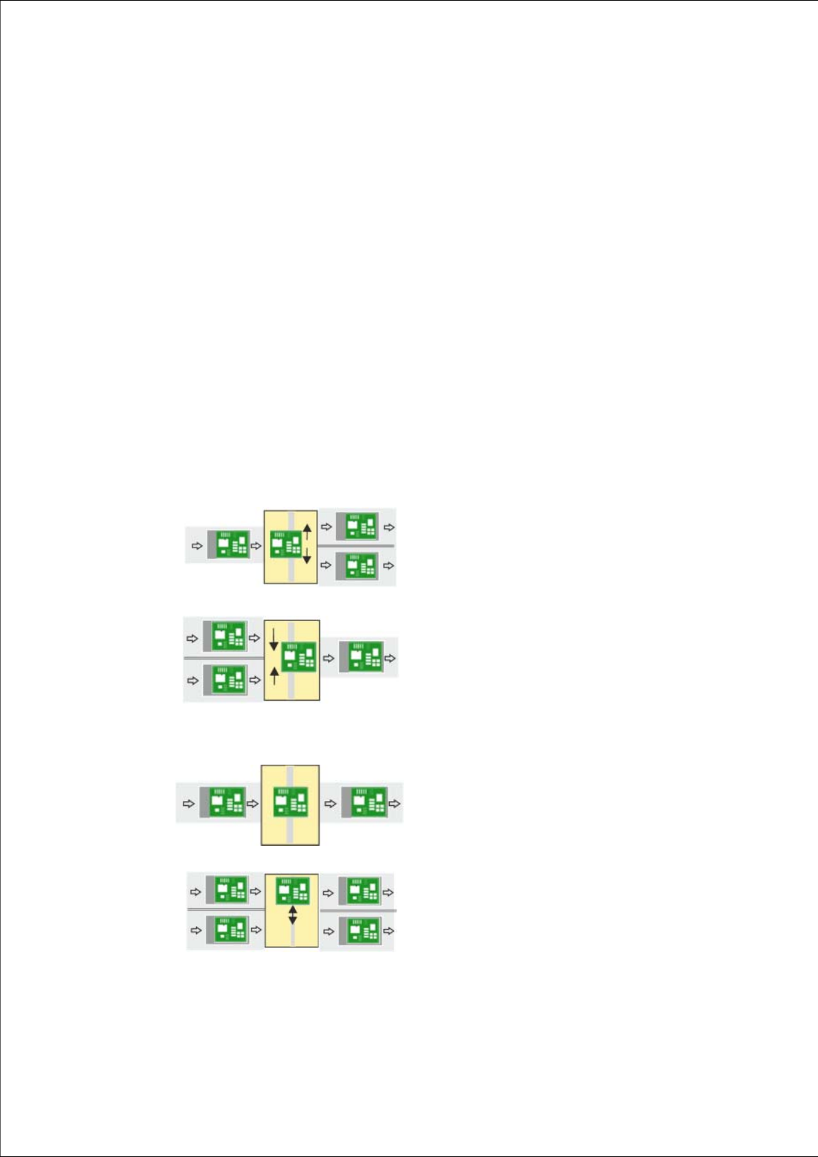
1
Single conveyor => Dual conveyor
Usually, the following right and then left conveyor lane are
used in alternation. However, if a conveyor lane is
blocked, the other lane can also be used several times in
succession.
1
Dual conveyor => Single conveyor
Usually, pickup is from the right and then the left conveyor
lane of the previous machine, in alternation. However, if
there is a problem at one lane or if there is no board
available, pickup can also be from the other lane several
times in succession. Precondition: the same product must
be produced on both lanes
1
Single conveyor => Single conveyor
The boards are transported through.
A displacement of the two machines can, for example, be
compensated for in this case.
1
Dual conveyor => Dual conveyor
Transfer of board with lane accuracy: The boards from
conveyor lane 1 are also transported in conveyor lane 1
of the next machine.
Usually, the conveyor lanes are used in alternation.
1 Introduction Assembly and User Manual SIPLACE TX
1.1 Description Shuttle Extension Edition 06/2017
6
As an example, the following scenarios are possible:
– SIPLACE TX with dual conveyor (I-Placement) on a SIPLACE SX with dual conveyor (alter
-
nating mode).
– SIPLACE TX with dual conveyor on a printer or furnace.
The Shuttle Extension TX is always fitted to the SIPLACE TX. There is also a Shuttle Extension
TX available for the output end and a Shuttle Extension TX for the input end.
Assembly and User Manual 1 Introduction
Shuttle Extension Edition 06/2017 1.2 Overview
7
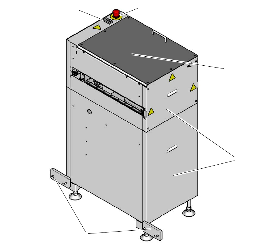
1.2 Overview
1.2.1 Shuttle Extension TX on SIPLACE TX Output Conveyor Side
1
Fig. 1.2 - 1 Shuttle Extension TX input side on SIPLACE TX output conveyor side
(T) Direction of travel from SIPLACE TX output conveyor
(1) Start- and Stop button
(2) EMERGENCY STOP button
(3) Top cover
(4) Side covers
(5) Interface brackets on SIPLACE TX output conveyor side
(1)
(5)
(2)
(3)
(4)