HS50_advance_level 2.pdf - 第99页
Stud ent Gu ide HS-5 0 Adva nced II 07/2 002 Ed ition 3 Power Supply 61 ➠ Connect th e placem ent sy stem t o the power supply . ➠ Measur e the voltages at the main power filter ’s input and o utput: 3 x 204 V AC / 3 x 2…
07/2002 Edition Student Guide HS-50 Advanced II
3 Power Supply
60
3DUWV
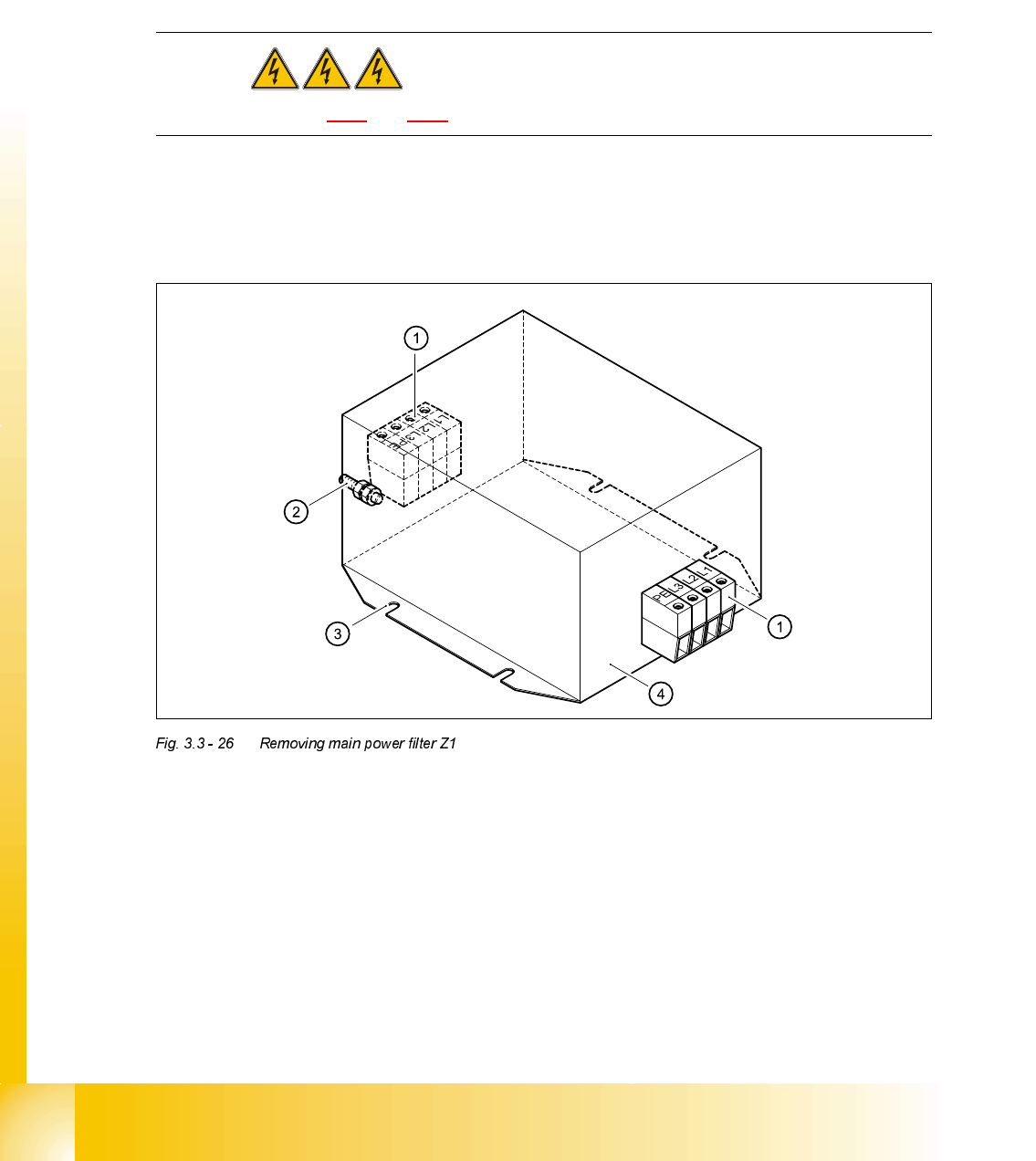
5HPRYLQJPDLQSRZHUILOWHU=
DANGER Switch off the placement system and disconnect from the power
supply (see sections 3.3.1 and 3.3.2).
➠ Loosen the clamping screws (1) for the terminal wires one by one and identify the terminal
wires with adhesive labels.
➠ Loosen the M6 hexagon nut (2) and pull out the protective earth cable.
➠ Loosen the M5 hexagon nuts (3) for fixing the main power filter.
➠ Remove the main power filter (4).
)LWWLQJWKHPDLQSRZHUILOWHU=
➠ Fit the main power filter (4) and fix in place with the M5 hexagon nuts (3).
➠ Attach the terminal wires (1).
➠ Attach the protective earth cable (2).
3RVLWLRQ 'HVLJQDWLRQ ,WHPQXPEHU
Z1 Main power filter for 36 A 3-phase systems 00342397-01
Student Guide HS-50 Advanced II 07/2002 Edition
3 Power Supply
61
➠ Connect the placement system to the power supply.
➠ Measure the voltages at the main power filter’s input and output:
3 x 204 VAC / 3 x 230 VAC / 3 x 380 VAC / 3 x 400 VAC / 3 x 415 VAC
➠ Complete the servicing work as described in 3.3.3 on page 3 - 29.
5HSODFLQJWKHLQUXVKFXUUHQWOLPLWDWLRQERDUG(67
7RROVDQGHTXLSPHQW
– Set of slotted-head screwdrivers
– Open-ended spanner or socket spanner, size 8
– Self-adhesive labels
– Digital voltmeter
3DUWV
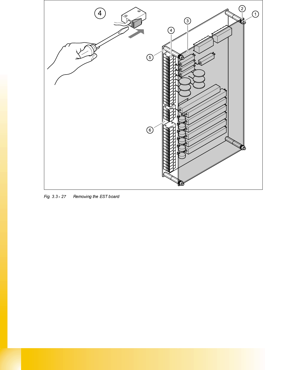
5HPRYLQJWKH(67ERDUG
DANGER Switch off the placement system and disconnect from the power
supply (see sections 3.3.1 and 3.3.2).
3RVLWLRQ 'HVLJQDWLRQ ,WHPQXPEHU
EST Inrush current limitation board TG 31033-01 00341831-01
07/2002 Edition Student Guide HS-50 Advanced II
3 Power Supply
62
➠ Loosen the M5 hexagon nuts (1) and remove together with the retaining rings (2).
➠ Remove the perspex panel (3).
➠ Detach the terminal wires from the terminal block one by one by pushing the terminal link (4)
in the direction indicated by the arrow.
➠ Identify the terminal wires with adhesive labels.
➠ Remove the M5 hexagon bolts.
➠ Remove the board.
)LWWLQJWKH(67ERDUG
➠ Fit the board and fix in place with M5 hexagon bolts.
➠ Connect up the terminal wires.
➠ Attach the perspex panel and fix in place with the retaining rings and M5 hexagon nuts.