HS50_advance_level 2.pdf - 第106页
1 - 4 07/2002 Editio n Student G uide HS -50 Advanc ed II Contents 4

3DJH
&RQWHQWV
Student Guide HS-50 Advanced II 07/2002 Edition
Contents
3
3QHXPDWLF
0DLQ3QHXPDWLF8QLW
9DFXXPV\VWHPRQWKH&3+HDG
4.2.1 Vacuum System . . . . . . . . . . . . . . . . . . . . . . . . . . . . . . . . . . . . . . . . . . . . . . . . . . . . . 7
4.2.1.1 Vacuum Pressure Measurement PCB . . . . . . . . . . . . . . . . . . . . . . . . . . . . . . . . . . . 8
4.2.1.2 Vacuum Measurement and Calculation at Reference Run . . . . . . . . . . . . . . . . . . . 9
4.2.1.3 Vacuum Check after Pick Up . . . . . . . . . . . . . . . . . . . . . . . . . . . . . . . . . . . . . . . . . 10
4.2.1.4 Vacuum Check before Placement . . . . . . . . . . . . . . . . . . . . . . . . . . . . . . . . . . . . . 11
4.2.1.5 Vacuum checks for check the valve plunger . . . . . . . . . . . . . . . . . . . . . . . . . . . . . 11
4.2.1.6 Vacuum Check "Segment Sealed" before Pick Up . . . . . . . . . . . . . . . . . . . . . . . . 12
4.2.1.7 Air Kiss at Placement or at Reject Position . . . . . . . . . . . . . . . . . . . . . . . . . . . . . . 13
4.2.1.8 Typical Vacuum Reference Run and Vacuum Values . . . . . . . . . . . . . . . . . . . . . . 14
7DSH&XWWHU
3&%6WRSSHU
1R]]OH&KDQJHU
&RPSRQHQW7DEOH

1 - 4
07/2002 Edition Student Guide HS-50 Advanced II
Contents
4
Student Guide HS-50 Advanced II 07/2002 Edition
4 Pneumatic
5
3QHXPDWLF
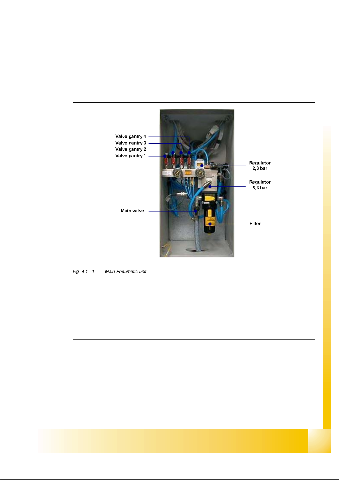
0DLQ3QHXPDWLF8QLW
The incoming air supply passes through the moisture trap filter into the main regulator. This reg-
ulator regulates the internal machine air pressure to 5.3 bar. Included within the regulator block is
a pressure sensor, which monitors the incoming air pressure. The analogue output of this pres-
sure sensor is supplied to an A/D converter which when the incoming pressure reaches 5.3 bar
gives an output of 24 VDC. This signal is supplied to the machine controller via the SLIO I/O func-
tion and the CAN-bus.
NOTE
This pressure sensor can be damaged if the machine is turned on without compressed air sup-
plied to it. Therefore if the compressed air supply fails, turn off the machine.
The 5.3 bar is supplied to the following elements: - The collect & place heads through a shut off
valve, the PCB stoppers, the nozzle changers, the tape cutters and the feeder tables.
A further adjustable regulator is used to reduce the 5.3 bar to 2.3 bar. This supply is used for the
supply air for the optional bulk case feeder rail.