HS50_advance_level 2.pdf - 第108页
07/2002 Editio n Student G uide HS -50 Advanc ed II 4 Pneum atic 6 9 DF XXPV\VWHPRQ WKH& 3+ HDG Bulk Case Supply Ga ntry 1 Ga ntry 2 Ga ntry 4 Ga ntry 3 B5.1 B5.4 B5.3 B5.2 B4 B7 B6 B2 S t op p er / Cu tt e…
Student Guide HS-50 Advanced II 07/2002 Edition
4 Pneumatic
5
3QHXPDWLF
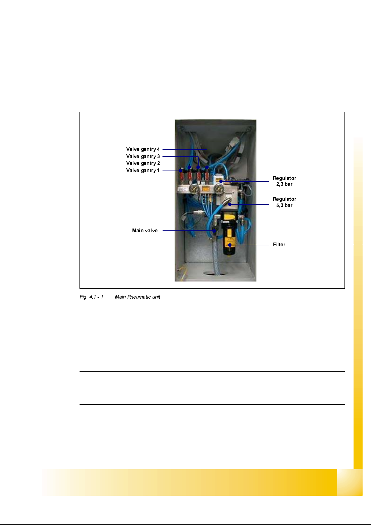
0DLQ3QHXPDWLF8QLW
The incoming air supply passes through the moisture trap filter into the main regulator. This reg-
ulator regulates the internal machine air pressure to 5.3 bar. Included within the regulator block is
a pressure sensor, which monitors the incoming air pressure. The analogue output of this pres-
sure sensor is supplied to an A/D converter which when the incoming pressure reaches 5.3 bar
gives an output of 24 VDC. This signal is supplied to the machine controller via the SLIO I/O func-
tion and the CAN-bus.
NOTE
This pressure sensor can be damaged if the machine is turned on without compressed air sup-
plied to it. Therefore if the compressed air supply fails, turn off the machine.
The 5.3 bar is supplied to the following elements: - The collect & place heads through a shut off
valve, the PCB stoppers, the nozzle changers, the tape cutters and the feeder tables.
A further adjustable regulator is used to reduce the 5.3 bar to 2.3 bar. This supply is used for the
supply air for the optional bulk case feeder rail.
07/2002 Edition Student Guide HS-50 Advanced II
4 Pneumatic
6
9DFXXPV\VWHPRQWKH&3+HDG
Bulk Case Supply
Gantry 1
Gantry 2
Gantry 4
Gantry 3
B5.1
B5.4
B5.3
B5.2
B4
B7
B6B2
Stopper / Cutter
B8
Nozzlechanger 2/3
B12.1
Nozzlechanger 1/4
Feeder Table 2/3
Feeder Table 1/4
B12.2
B13.1
B13.2
not used
not used
B10
B11
6,5 - 8 bar
main valve
filter
5,3 bar
2,3 bar
Student Guide HS-50 Advanced II 07/2002 Edition
4 Pneumatic
7
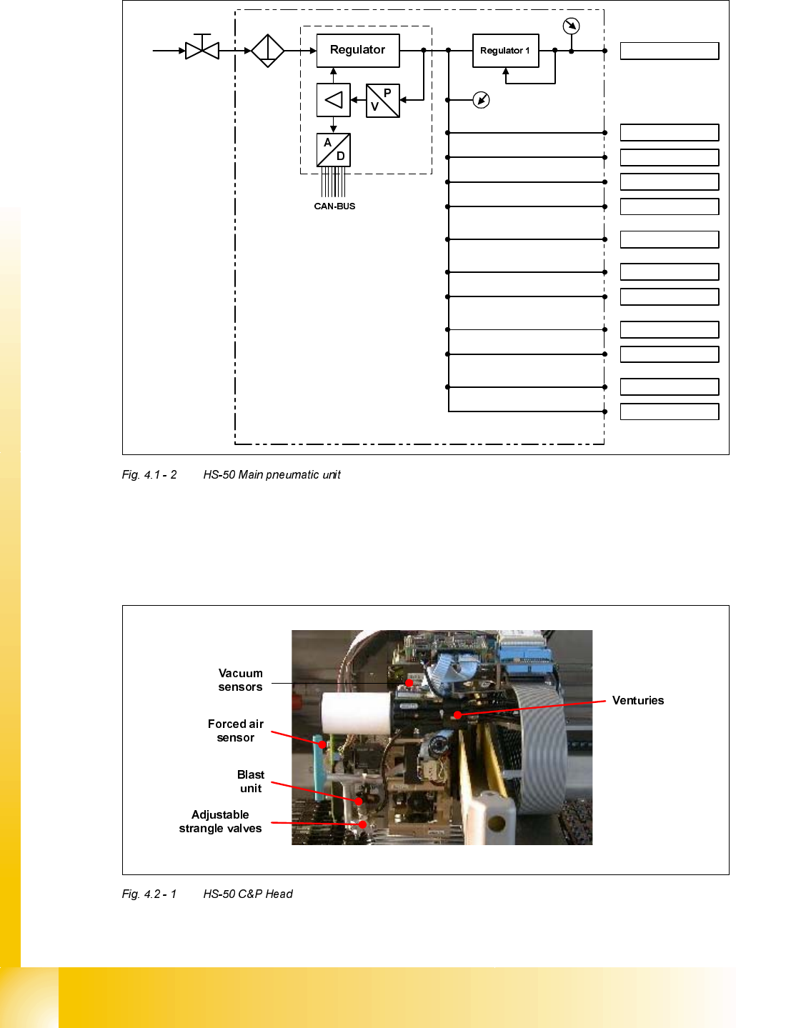
The air is supplied to the collect & place head in several pipes, each of which is supplied with a
5.3 bar pressure. All pipes are labelled and should be attached to the head as shown in the dia-
gram above.
The air supply at the collect & place head is used for two principle things, vacuum generation and
air kiss.
9DFXXP6\VWHP
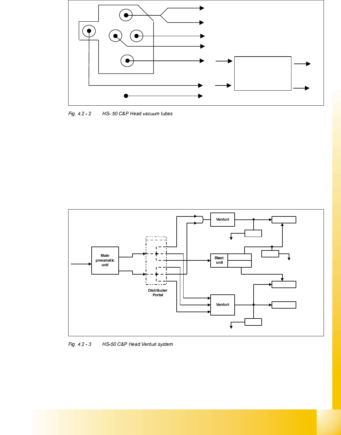
The air is supplied to the venturi block, which produces a vacuum using the venturi principle. The
venturi block actually consists of 2 separate venturi which produce vacuum for 2 circuits, the hold-
ing circuit and the pick up / placement circuit.
EOLQG
33
quadruplicate distributor
below head board
4
4
E2
E1
6,5 - 8 bar
E3
B5.1 or
B5.2 or
B5.3 or
B5.4
A1
A4
A6
A2
A5
A3
A7
Adjustable
valve
Adjustable
valve
Valve plunger
Holding
circuit
Valve plunger
Valve plunger
Vacuum
sensor
To vacuum board
Reject
circuit
Vacuum
sensor
To vacuum board
Forced air
sensor
to adapter board
Pickup /
placement circuit
forced air
0.2 - 0.3 bar
forced air
0.15 - 0.2 bar