HS50_advance_level 2.pdf - 第111页
Stud ent Gu ide HS-5 0 Adva nced II 07/2 002 Ed ition 4 Pneum atic 9 9 DFXXP0 HDVXUHPHQWDQG &DOFXODWLRQDW 5HIHUHQFH 5XQ 1. T wo vacuum measu rements are ma de at r eference . 1st with valv e close d and…

07/2002 Edition Student Guide HS-50 Advanced II
4 Pneumatic
8
The level of vacuum produced is dependant on a number a factors the most obvious of which is
the condition of the venturi itself. Any leakage from or blockage within the system will result in it
working inefficiently and therefore a reduction in the vacuum levels created. Therefore it is impor-
tant that the venturi is correctly sealed when reassembled and that the condition of the nozzles
within the system is good.
There are other factors that will affect the vacuum levels generated that are beyond your control
however. The most significant of these is altitude. The higher above sea level a machine is located
the lower the ambient pressure in the room surrounding it is. Therefore at high altitude low vacuum
levels are created, an example is a machine in Munich, Germany at an altitude of 500m may gen-
erate closed vacuum results of 870 mB whereas the same machine at almost sea level in the UK
would generate vacuum results of 920mB.
The other factor that can result in lower vacuum results is the weather. On a stormy rainy day a
Low pressure system will be present and may result in closed vacuum results of 880 mB. A week
later a bright sunny day results due to a High-pressure system. In this case closed vacuum results
of 900 mB may result.
These 2 cases are only examples and no specific case / figures are used, but this just illustrates
what can happen. In these cases it becomes even more important that the venturi system is well
maintained and therefore performing efficiently.
9DFXXP3UHVVXUH0HDVXUHPHQW3&%
A small PCB mounted on the venturi block measures the vacuum pressure within the holding and
pick up / placement circuits. Small tubes are attached to the back of the collect & place head that
mea-sure the circuit pressures at the vacuum distributor. These tubes are connected to pressure
sen-sors. The analogue outputs of these sensors are supplied to A/D converters. The resulting
signals are then sent via the CANBUS to the machine controller.
Student Guide HS-50 Advanced II 07/2002 Edition
4 Pneumatic
9
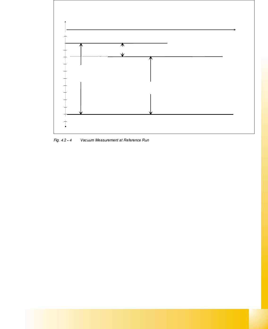
9DFXXP0HDVXUHPHQWDQG&DOFXODWLRQDW5HIHUHQFH5XQ
1. Two vacuum measurements are made at reference. 1st with valve closed and 2nd with the
value open and air passing through the nozzle.
2. The closed value is dependant on the environment pressure which can vary greatly, depending
on local weather conditions and altitude. Basically the higher the altitude the lower the environ-
mental pressure therefore the lower the closed vacuum.
3. The open value is dependant on nozzle size and nozzle condition. The smaller the nozzle the
larger the open value. In the same way a contaminated or blocked nozzle will also give a large
open value.
4. The difference between open and closed nozzles as a minimum value is pre determined by the
line computer generated ideal.MA. This is different for all nozzle types. E.g. 120 mbar for 714,
704, 914 and 904 nozzle. If these values cannot be reached, the error message "Intervals be-
tween open/closed insufficent" will appear.
5. The threshold for component acceptance is determined at this time. In this case we have an
open value of 700 mbar, and a closed value of 900 mbar. The calculation is shown below.
Threshold = (900(closed) - 700(open)) x 0.2 + 700(open)
= 200 x 0.2 + 700
= 740
-700
-720
-740
-760
-780
-800
-820
-840
-860
-880
-900
0
t
PD[LPXPYDFXXP
9DFXXPQR]]OHFORVHG
9DFXXPQR]]OHRSHQ
7KHGLIIHUHQFHLQWKHUHVXOWVRIWKH
YDFXXPPHDVXUHPHQWVVKRXOGODUJHU
WKDQWKHPLQLPXPYDOXHIURP/&
(QYLURQPHQWSUHVVXUH
IRUUHMHFW
IRUDFFHSWDQFH
DWYDFXXPFKHFN
7KUHVKROG YDFFORVHGYDFRSHQ[YDFRSHQ
3UHVVXUHGLIIHUHQFHQR]]OHLQVLGH!HQYLURQPHQW
07/2002 Edition Student Guide HS-50 Advanced II
4 Pneumatic
10
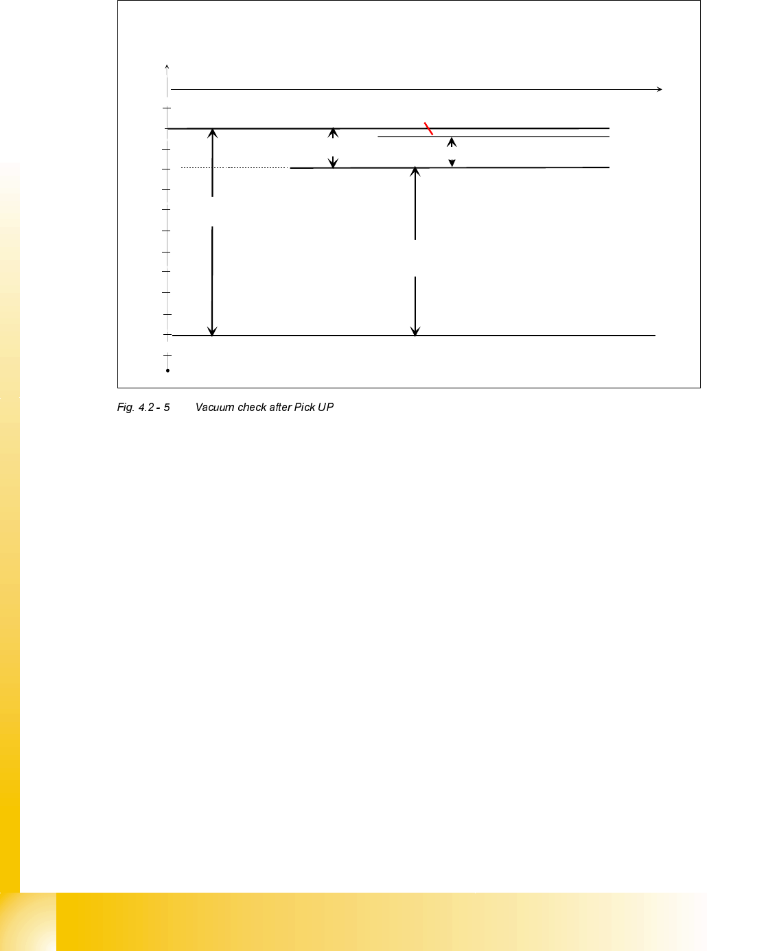
9DFXXP&KHFNDIWHU3LFN8S
1. The first vacuum check is made after pick up when the z axis is in the upper position.
E\DFKLHYHWKHXSSHUOLJKWEDUULHU
2. The second vacuum check is made after pick up when the z axis is in the upper position
E\DFKLHYH= .
3. The component is accepted if the result is within 80% of the nozzle open/closed result deter-
mined during reference.
4. The component is rejected if the result is within 20% of the nozzle open/closed result.
5. The component is immediately re-picked if the result is within 5 mbar of the open value (the
machine assumes no component present).
6. Otherwise the head is moved to the reject bin and the component rejected with air kiss.
-700
-720
-740
-760
-780
-800
-820
-840
-860
-880
-900
0
t
PD[LPXPYDFXXP
9DFXXPQR]]OHFORVHG
9DFXXPQR]]OHRSHQ
9DFXXPGLIIHUHQFHDW
WKHODVWUHIHUHQFHUXQ
(QYLURQPHQWSUHVVXUH
&RPSRQHQWLVUHMHFWHGDWUHMHFWER[
&RPSRQHQWLVDFFHSWHG
DWYDFXXPFKHFN
&RPSLVUHMHFWHG
&RPSRQHQWLPPHGLDWHO\UHSLFNHG
PEDU
3UHVVXUHGLIIHUHQFHQR]]OHLQVLGH!HQYLURQPHQW