HS50_advance_level 2.pdf - 第145页
Stud ent Gu ide HS-5 0 Adva nced II 07/2 002 Ed ition 6 Control & Co mmunicatio n 15 'LJLWL] DWLRQDQG 0XOWLSOL FDWLRQ RIWKH $ QDORJXH7 UDFN6LJ QDOV Phase s hift check on pos sible c ount err ors.…
07/2002 Edition Student Guide HS-50 Advanced II
6 Control & Communication
14
'LJLWL]DWLRQRI7UDFN6LJQDOV
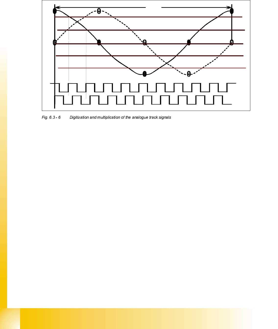
Digitization and multiplication of the analogue track signals.
The electronic multiplication of the track signals is based on the voltage level and on the phase
shift of the two track signals (the drawing is simplified). There is a Schmitt Trigger circuit with
phase check and this digitizes and multiplies the analogue track signals. These pulses have a fre-
quency of 25 times that of the analogue waveform with each pulse formed as the analogue wave-
form passes certain predetermined voltage levels.
5,12 ms
0,512 ms
Student Guide HS-50 Advanced II 07/2002 Edition
6 Control & Communication
15
'LJLWL]DWLRQDQG0XOWLSOLFDWLRQRIWKH$QDORJXH7UDFN6LJQDOV
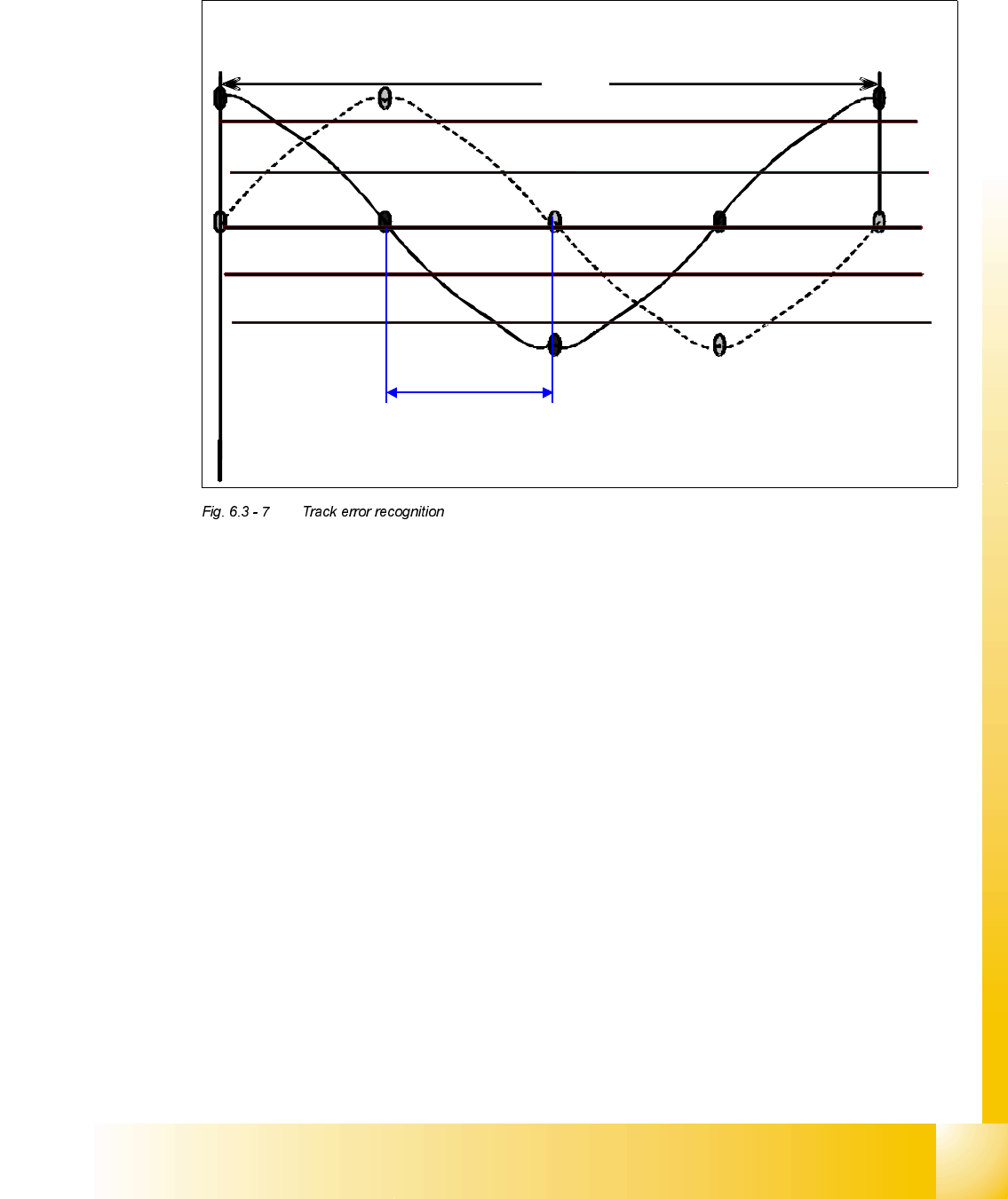
Phase shift check on possible count errors.
7UDFNHUURUUHFRJQLWLRQDWDQDORJXHVLJQDO
5,12 cm
The tolerance at the analogue signal of the track signal is checked according the limit of
90° +/- 15°
90° +/- 15°.
07/2002 Edition Student Guide HS-50 Advanced II
6 Control & Communication
16
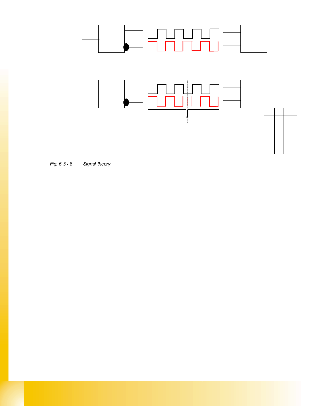
7UDFN$DQG,QYHUWHG$VLJQDOWKHRU\$OVRIRU%DQG,QYHUWHG%
The track signal A is prepared to be send down to axis controller
= 1
A
∀
A
A buffer and an inverter amplifies the rectangular track signal A and the inverted signal
∀.
To detect a transmission error in the machine we invert the generated track signal. If the
two signal lines at axis controller always have an inverted state the count pulses are
correct.
= 1
A
∀
A
If an error occurs in the wiring the EXOR logic (exclusive OR logic gate)
recognizes this. Therefore the axis card will signal a counting error.
A
∀
Q
0 0 0
0 1 1
1 0 1
1 1 0
Output