HS50_advance_level 2.pdf - 第147页
Stud ent Gu ide HS-5 0 Adva nced II 07/2 002 Ed ition 6 Control & Co mmunicatio n 17 =HUR3XO VH7K HRU\ The Zero pulse of th e axes is a singul ar sign al in th e whole tr avel ran ge. This define s the “ho …
07/2002 Edition Student Guide HS-50 Advanced II
6 Control & Communication
16
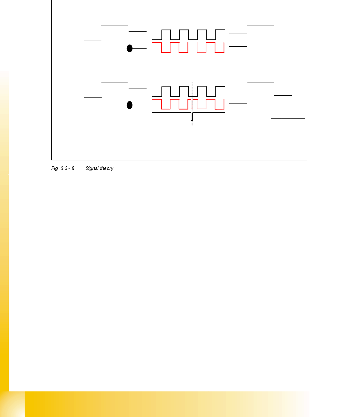
7UDFN$DQG,QYHUWHG$VLJQDOWKHRU\$OVRIRU%DQG,QYHUWHG%
The track signal A is prepared to be send down to axis controller
= 1
A
∀
A
A buffer and an inverter amplifies the rectangular track signal A and the inverted signal
∀.
To detect a transmission error in the machine we invert the generated track signal. If the
two signal lines at axis controller always have an inverted state the count pulses are
correct.
= 1
A
∀
A
If an error occurs in the wiring the EXOR logic (exclusive OR logic gate)
recognizes this. Therefore the axis card will signal a counting error.
A
∀
Q
0 0 0
0 1 1
1 0 1
1 1 0
Output
Student Guide HS-50 Advanced II 07/2002 Edition
6 Control & Communication
17
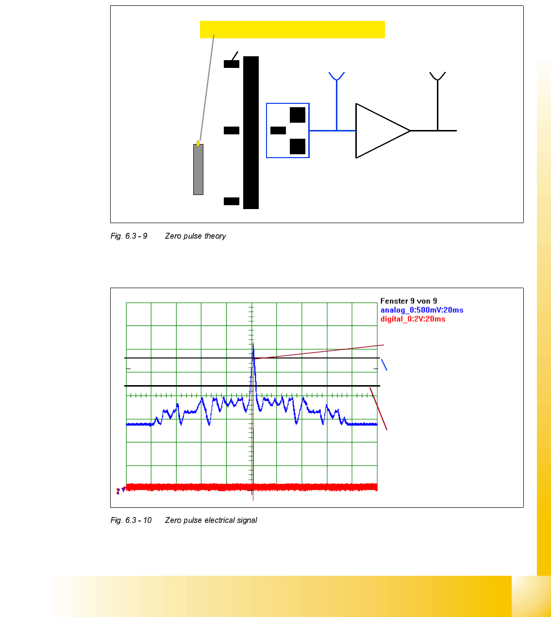
=HUR3XOVH7KHRU\
The Zero pulse of the axes is a singular signal in the whole travel range. This defines the “home
position” where position counting starts. On the X & Y axes the Zero pulse is repeated within the
travel range, however only one signal is used. During the reference run this zero pulse window is
detected with help of proximity switches (Bero).
=HURSXOVHHOHFWULFDOVLJQDOVHHQRQDQRVFLOORVFRSH
Zero pulse window (repeated)
Proximity switch (Bero)
At 2,7 V the Schmitt Trigger-
circuit generates the digital
Zero pulse signal.
The analogue Zero pulse
should override this threshold.
Interference pulses should not
override this limit.
07/2002 Edition Student Guide HS-50 Advanced II
6 Control & Communication
18
)XQFWLRQLQJRIWKH$[HV%RDUGV
$[LV6HUYR&DUG3ULQFLSOHV
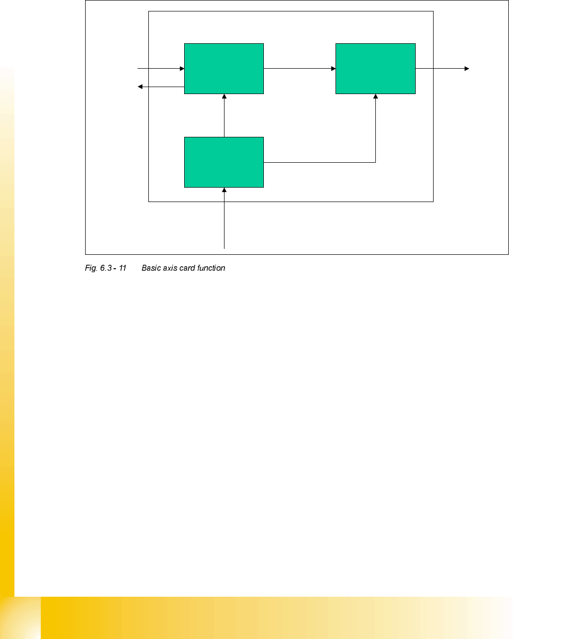
Basic axis card function
The axis boards control the movement of the axes. The axis controller receives commands and
the necessary parameters via SMP bus connection from the MC. In the same way an end signal
is returned to the MC. The axis controller outputs a direct voltage to the speed controller in the
servo amplifier (V nom). The voltage level and the polarity here determine the speed of movement
and the direction.
An additional voltage (force) is supplied to the servo amplifier which is used to set the force limit
during Z-axis movement. Also with this output we generate another signal to speed up the accel-
eration and deceleration phase of X and Y (S2x) axis movement.
The current position of the axis is determined by means of the incremental path / angle measure-
ment system (track signals).
7KHD[LVFRQWUROOHUFRQVLVWVRIDSRVLWLRQDQGVSHHGGHWHFWLRQV\VWHP
This system uses the track signals produced by the encoder system. Within the system the posi-
tion counter is used to detect the current position. An overshoot counter is used during the final
positioning of the axis to monitor any overshoot passed the target position.
There is a speed detection system on the axis controller to prevent the axis from a crash situation
because of too high an axis speed. (info see error message "axis tachointerrupt")
Position Control
System
Speed Control
System (not for
Z axis)
Position and speed
detection system
Control signals
to & from
machine
controller
via SMP BUS.
Track signals from encoder system
Analogue
Signals to Servo
Card
( V nom + force
)