HS50_advance_level 2.pdf - 第152页
07/2002 Editio n Student G uide HS -50 Advanc ed II 6 Cont rol & C ommun icatio n 22 0RWRUFXU UHQWFRQ WUROORRS DQG FRPSDU DWRU The output of the Axis co ntrol ler produc es the Nom inal valu e (I nom_U / I nom…
Student Guide HS-50 Advanced II 07/2002 Edition
6 Control & Communication
21
0RWRUFXUUHQWFRQWUROORRSDQGFRPSDUDWRU
The output of the RPM controller produces the set point value for motor current controller loop.
The output of the servo system is fed back current controller loop in order to control the limit of the
motor current. An additional element is the input of the force voltage from the axis controller, which
is used to provide the current limit for the axis movement. An additional element for the X & Y axis
is the (additional) speed signal given by the force input of the servo amplifier to boost the accel-
eration and deceleration. Fixed value resistors limit the maximum motor current and they are
specified by the motor data.
0RWRUFRQWUROV\VWHP3RZHUVWDJH
Here the motor current is controlled to directly affect the motor speed. The output signal of the
current controller is amplified here and fed to the power semiconductors to generate the motor
current. (See Power supply).
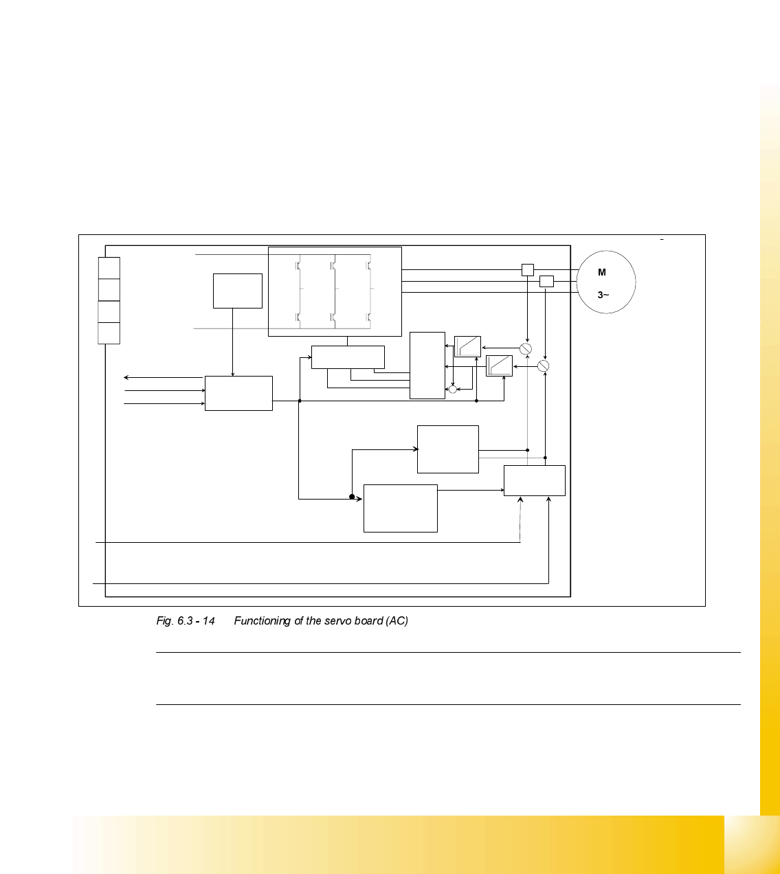
)XQFWLRQLQJRIWKH6HUYR%RDUG$&
NOTE
The AC Servo card produces the 3 phase AC voltage from the DC voltage inputted into the card.
The third
current signal
is generated on
servo board:
0 - I
L1
- I
L3
= I
L2
Inverter
+
-
+
-
current controlling signal input I
u
/ I
w
current pulse
limiter
I RMS current
limiter
current
commutation
controller
pulse-
witdth-
modulation
over- under
voltage
over current
power stage
operational
controlling
and error logic
2 current controller
Enable start enable
controlling dynamic brake
power supply
readyt
Servo ON
I RMS
error
fatal
error
Inverter

07/2002 Edition Student Guide HS-50 Advanced II
6 Control & Communication
22
0RWRUFXUUHQWFRQWUROORRSDQGFRPSDUDWRU
The output of the Axis controller produces the Nominal value (I
nom_U
/ I
nom _W
) for motor current
controller loop. The output of the servo system is fed back current controller loop in order to control
the limit of the motor current. Fixed value resistors limit the maximum motor current and they are
specified by the motor data. Additionally the I2t current control loop checked the nominal value (I
nom_U
/ I
nom_W
) which are coming from the Axis controller.
The nominal value (I
nom_U
/ I
nom _W
) put themselves together as follows (axes controller):
theoretical value which results from calculation of the speed profil.
Deviation of the speed controller.
Deviation of the velocity control unit.
Deviation of the position controller.
Deviation is formed from the actual signals (Track signals A and B) and the target position.
0RWRUFRQWUROV\VWHP3RZHUVWDJH
Here the motor current is controlled to directly affect the motor speed. The output signal of the
current controller is amplified here and fee to the 3 phase power semiconductors to generate the
AC-motor current. The current controller is a PI controller and performs the coarse positioning of
the axis, there he through its integration part most rapid to deviations may react control.
Student Guide HS-50 Advanced II 07/2002 Edition
6 Control & Communication
23
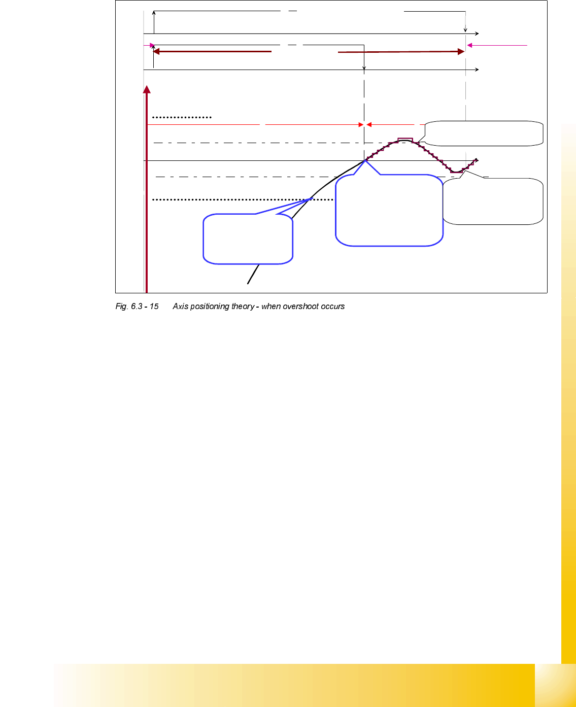
$[LV3RVLWLRQLQJ7KHRU\ZKHQ2YHUVKRRW2FFXUV
([SODQDWLRQRI7HUPV
3RVLWLRQLQJ0RGH
This means moving the axis mechanism out of the current position in a specified destination po-
sition under controlled acceleration and speed control. Here the destination position, the acceler-
ation, the deceleration and the speed can be varied.
$OORZHGGHYLDWLRQRISRVLWLRQ
The end signal is generated, when the position deviation is in the allowed range (value in
ACHS.MA, normally 13 digits).
3RVLWLRQLQJ&RUULGRU
By crossing the positioning corridor (digit value in ’mode 2’ in ACHS.MA, normally 10 digits) the
set point speed is set to zero (Vnull) and the position control is activated. This means the micro-
processor calculates the acceleration and deceleration curve to a position, which is 10 digits be-
fore the real target position.
2YHUVKRRW&RXQWHUDQG(QG6LJQDO
The Overshoot counter is activated when the axis crosses the target (setpoint) position for the first
time. You can check this overshoot because axis test box is triggered with "actual position is nom-
inal position signal". The End signal is given by the axis card to the Machine Controller once the
apex of the overshoot is within the Allowed Deviation of position. The end signal allows the ma-
chine controller to initiate the next movement or function.
Position counting
Overshoot
counting
Time
Time
Time
mechanical movement and position counting
ACTUAL-, is NOMINAL position signal
End signal
Allowed deviation of position
Allowed deviation of position
positioning
occurrence
position
controlling
X
position
Axis move up from
here with minimum
speed and with
reduced P
gain
When the mechanic move
the first time across the
target position the
“actual position is nominal
position signal” is triggered
the overshoot counter starts
The overshoot counter monito
r
a 6 digit maximum
End signal is triggered
position controlling start
s
and the next axis starts
For the P&P head is the allowed deviation of position 2 digit
Positioning
corridor