HS50_advance_level 2.pdf - 第158页
07/2002 Editio n Student G uide HS -50 Advanc ed II 6 Cont rol & C ommun icatio n 28 $ QWL&UDVK It checks the ratio of th e actual sp eed to the r emain ing brak ing distance. If the ratio bec omes too large t…
Student Guide HS-50 Advanced II 07/2002 Edition
6 Control & Communication
27
$GGLWLRQDO$[LV&RQWURO&RPSRQHQWV
'\QDPLF%UDNH
The X and Y axes of both gantries are operated with a dynamic brake. This module is located be-
side the corresponding servo board. The dynamic brake brings axis to an immediate stop when
there is a crash risk, voltage drop or when there is a fault in the servo amplifier, independently of
the control system. This is breaking is performed by means of two thyristors (silicon controlled rec-
tifier) in inverse parallel connection which shunt out the motor inductivity via protective series re-
sistors. Gate control via servo board.
NOTE
At E-Stop servo disable is delayed until the deceleration slope is finished.
0HWKRGRIIXQFWLRQLQJ
When the servo board is ready for operation the relay on the brake module is supplied with current
and keeps the thyristor in the inhibited state. If there is a voltage drop, the servo board deactivated,
the amplifier output stage in the servo board will be de-energized, the relay drops out and one of
the two thyristors fires. The motor is now shunted via the series resistors contained in the brake
module.
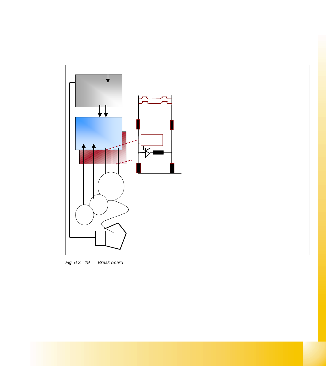
Break board for gantry axes
½ The gantry axes of all machines have a
break board beside the servo amplifier.
½ If a crash or a servo fault happens the
inductivity of the axis drive is short
circuited by this board.
½ The break board is active when the
servo enable signal is OFF.
½ This function is also active when you
move the axis manually faster than a
predefined speed limit.
½ The enable signal from axis controller to
servo amplifier is wired via break
board.
A/B
Brake board
One phase (of
three) short circuit
on the break board.
controlled by
Servo amplifier
Output
inductivity
servo
Motor
inductivity
Axis
controller
Servo
amplifier
M 3~
G3~
RPE

07/2002 Edition Student Guide HS-50 Advanced II
6 Control & Communication
28
$QWL&UDVK
It checks the ratio of the actual speed to the remaining braking distance. If the ratio becomes too
large then the servo enable signal is deactivated and the dynamic break activated (the corre-
sponding LED goes dark).
With help of the distance sensor we measure this speed to breaking distance ratio between the
two gantries. If the speed is too high according the distance to the other gantry all gantry axis ser-
vos are disabled by the anti crash board.
The travel range proximity switches (Bero), for X and Y-axis, measure this speed to breaking dis-
tance ratio referring to the limit switches or the bumpers. If the speed is to high in the area where
only one of "bero´s" is on this servo controller is disabled and dynamic break activated.
The proximity switches are connected to the axis controller as well as to the anti crash board. This
is necessary for the speed check.

;$[LV