HS50_advance_level 2.pdf - 第165页
Stud ent Gu ide HS-5 0 Adva nced II 07/2 002 Ed ition 7 X- Axis 7 6 WUXFWXUHR IWKHJDQWU\ The princ ipal ele ment of the gantry is the to rsiona lly ri gid prec ision-c ast gan try . D iagram 7.2 - 1 contains a pla…
07/2002 Edition Student Guide HS-50 Advanced II
7 X-Axis
6
The structure of the gantries makes them very torsionally rigid. Precise mechanical movements
of the axes are produced by axis recirculating ball screw units.
High-precision positioning systems determine the positions of the x and y axes. To do this, the
graduations on metal scales are optoelectronically scanned and the track signals are sent to the
axis control in the control unit.
Direct drive units are used to position the placement heads in the x and y directions. This elimi-
nates friction losses, for example, which are typical when complex gearing is used. In addition,
there is none of the wear that can significantly affect the accuracy of positioning systems over the
course of time.
;D[LVGULYH
A toothed belt is used to convert the rotary movement of the turning motor for the X-axis directly
into a translatory movement of the placement head in the x direction.
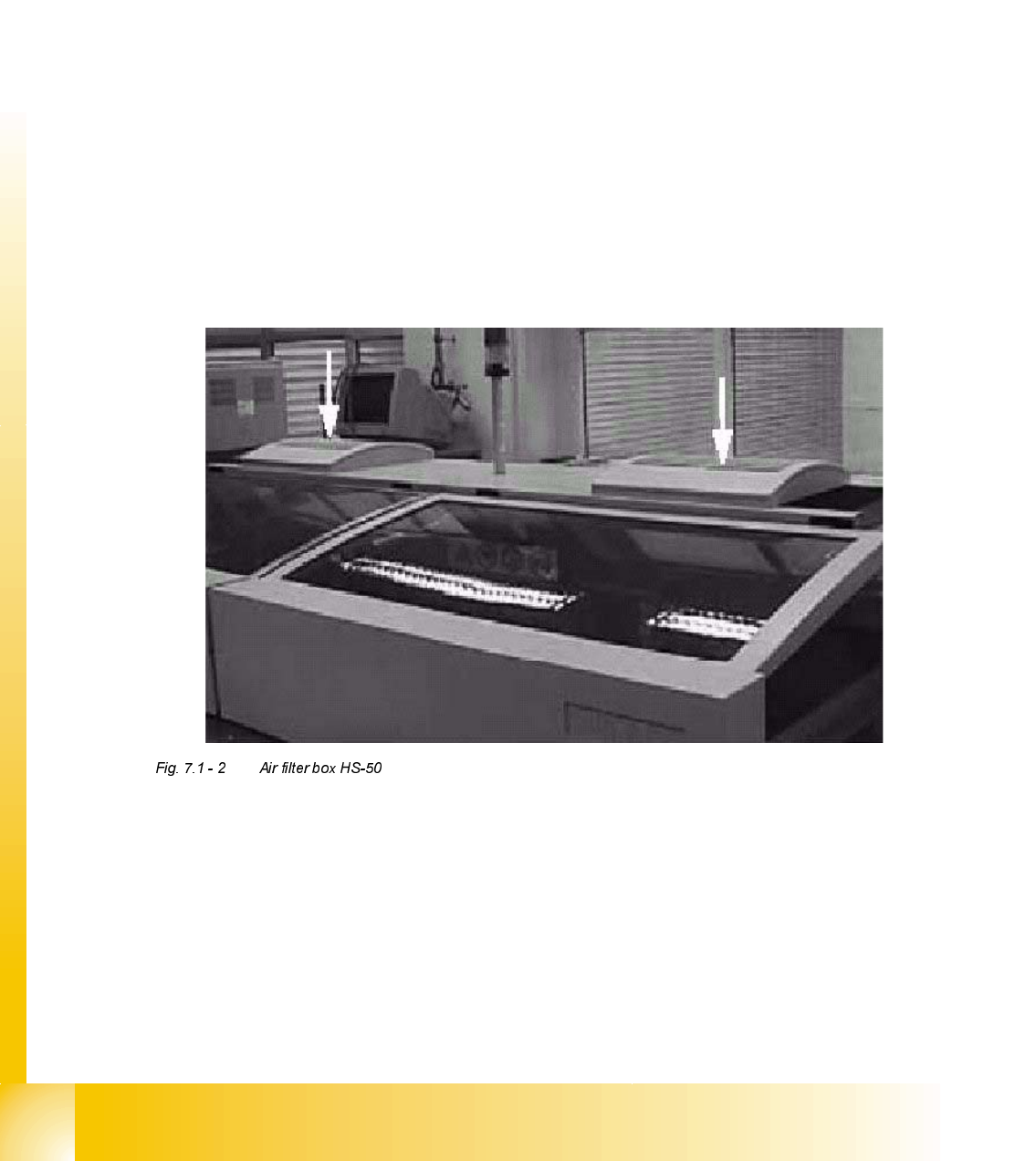
2SWLRQ$LUILOWHUER[IRU;0RWRUV
The air filter box for the X-motors, consisting of one filter and two highperformance fans, is
mounted directly above the cooling air inlet of the linear motor.
– Sleeve contamination is reduce by 20%
– Contamination of valve tappets is reduce by 40%
– The frequency of maintenance require is reduce by 30%
Student Guide HS-50 Advanced II 07/2002 Edition
7 X-Axis
7
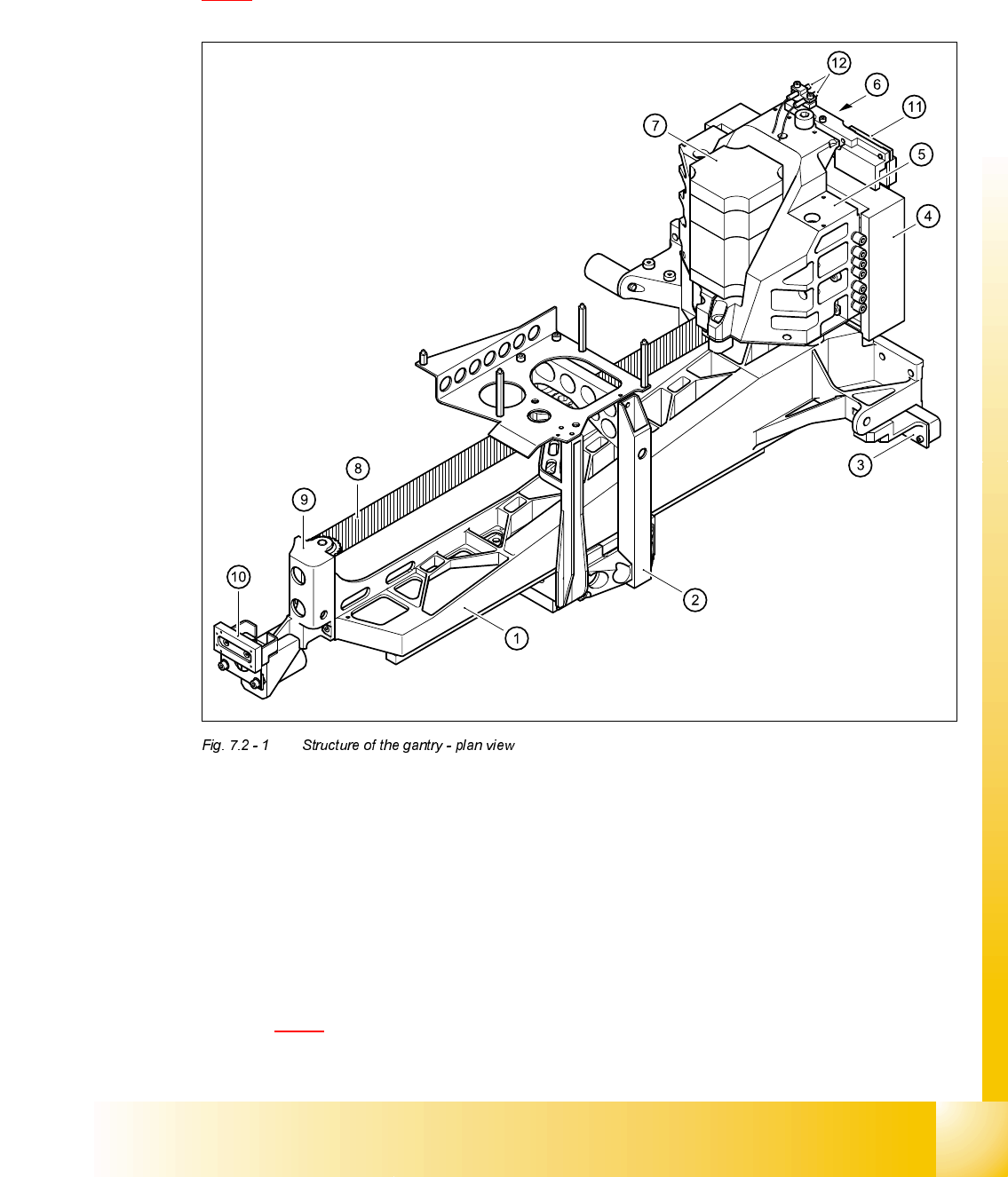
6WUXFWXUHRIWKHJDQWU\
The principal element of the gantry is the torsionally rigid precision-cast gantry. Diagram
7.2 - 1
contains a plan view of its major components.
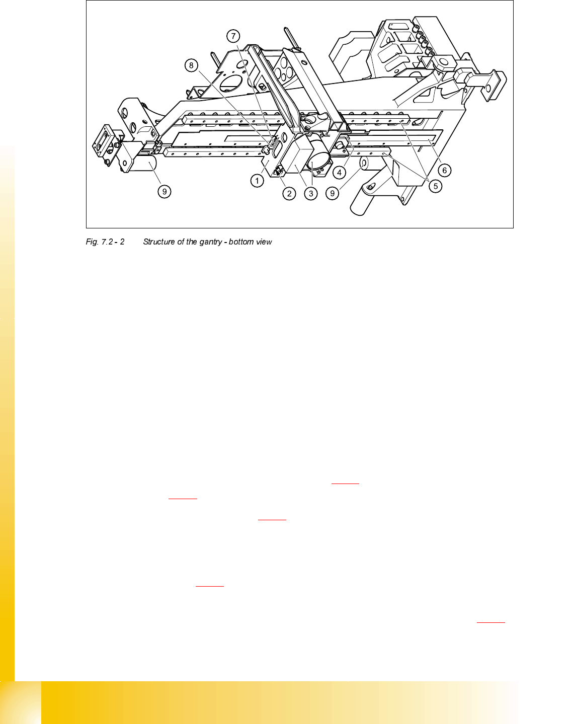
Diagram 7.2 - 2 shows a bottom view of the gantry.
(1) Precision-cast gantry (2) Head mount
(3) Incremental encoder for Y-axis scale (4) Primary part of the y linear motor
(5) Motor bracket (6) Thrust bearing
(7) X-axis motor unit (8) Toothed belt
(9) Deflection unit (10) Y-axis brake, external
(11) Y-axis brake, internal (12) Proximity switches B1 and B2 for the Y-axis
07/2002 Edition Student Guide HS-50 Advanced II
7 X-Axis
8
The gantry is fixed to the two shuttles (see item 1 in Fig. 7.2 - 3) of the recirculating ball screw unit
(see item 2 in Fig. 7.2 - 3
) using four M6 x10 hexagon socket-head screws.
The secondary part (see item 3 in Fig. 7.2 - 3
) of the Y-axis linear drive, with its permanent mag-
nets, is located above the guide rail of the recirculating ball screw unit. The secondary part is
mounted on the machine frame.
The air and power supply and signal lines for the gantry and collect&place head all run in a trailing
cable (see item 1 in Fig. 7.2 - 4
).
The seven power cables take the form of flexible ribbon cables, four of which are needed for the
collect&place head. They run beneath the cover in the machine frame (see item 1 in Fig. 7.2 - 5
),
between the head board on the head mount and the gantry board.
(1) Head mount
(2) X-axis brake
(3) PCB camera with lens system
(4) Incremental encoder for the X-axis
(5) Recirculating ball screw unit KUME 12B
(6) Scale for the X-axis
(7) End position proximity switch 2
(8) End position proximity switch 1 and reference point for the X-axis
(9) Elastomeric spring 25x10.5x50