HS50_advance_level 2.pdf - 第175页
Stud ent Gu ide HS-5 0 Adva nced II 07/2 002 Ed ition 7 X- Axis 17 5HSODFLQ JVS DUHS DU W V 5HS ODFLQJWK HHODV WRPHULFVS ULQJ 7 RROVDQGHTXLSP HQW – Set of DIN 9 1 1 All en keys …

07/2002 Edition Student Guide HS-50 Advanced II
7 X-Axis
16
– The Tag Out alternative:
If a machine can be locked out, it must be. However, there are situations where energy isolat-
ing devices can not accommodate locks. In these cases, the energy isolating devices must be
tagged to warn employees that the machine is de-energized for servicing. The tag must be se-
curely fastened, it must be placed in a position visible to all and it may only be removed by the
person who attached it.
WARNING
To avoid damaging the collect&place head, ALWAYS observe the following points when mov-
ing the gantry:
– NEVER move the gantry by pushing with your hands against the collect&place head.
– NEVER push the gantry while the Z-axis is lowered.
– Take hold of the cast iron part of the X-axis - ideally near the X-axis toothed belt deflection
pulley - and then move the gantry.
Student Guide HS-50 Advanced II 07/2002 Edition
7 X-Axis
17
5HSODFLQJVSDUHSDUWV
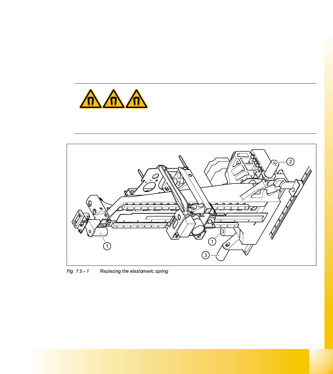
5HSODFLQJWKHHODVWRPHULFVSULQJ
7RROVDQGHTXLSPHQW
– Set of DIN 911 Allen keys
3DUWV
25x10.5x50 elastomeric spring, from item number 00301040-01
5HPRYLQJWKHHODVWRPHULFVSULQJ
➠ Switch the placement system off and secure it to prevent switching on again.
DANGER POWERFUL MAGNETIC FIELD
Always follow the special safety instructions when working in the vicinity of powerful magnetic
fields.
1 Elastomeric springs for the X-gantry
2 Gantries 1 and 3: elastomeric spring for the Y-axis
Gantries 2 and 4: reflecting bracket instead of elastomeric spring
3 Gantries 1 and 3: elastomeric spring for the Y-axis
Gantries 2 and 4: item 3 canceled

07/2002 Edition Student Guide HS-50 Advanced II
7 X-Axis
18
➠ Loosen the M8x20 hexagon socket-head screw in the hole in the elastomeric spring.
➠ Push the metal sleeve out of the elastomeric spring.
,QVWDOOLQJWKHHODVWRPHULFVSULQJ
➠ Insert the metal sleeve into the new elastomeric spring.
➠ Use the M8 x 20 hexagon socket-head screw to fix the elastomeric spring.
6HWWLQJV
None
5HSODFLQJWKHWHQVLRQLQJNH\V
7RROVDQGHTXLSPHQW
– Set of DIN 911 Allen keys
– TSM belt tension measuring device, from item number 00326015-01
– "Measuring belt tensions" operating instructions
Parts
'HVLJQDWLRQ )URPLWHPQXPEHU ,WHPLQ)LJ
Tensioning key 00329478-01 (1)
Tensioning key 00329485-01 (2)
5HPRYLQJWKHWHQVLRQLQJNH\V
➠ Switch the placement system off and secure it to prevent switching on again .
➠ Push the head mount towards the deflection pulley (item 6 in Fig. 7.5 - 2).
➠ To slacken the toothed belt (item 5 in Fig. 7.5 - 2)
– loosen the locknut (item 11 in Fig. 7.5 - 2
) and
– turn the hexagon socket-head screw counter-clockwise (item 3 in Fig. 7.5 - 2
).
5HPRYLQJWKHWHQVLRQLQJNH\LWHP V\QFKURQL]LQJGLVNVKRUW
➠ Loosen the M4 x 5 hexagon socket-head screw (item 8 in Fig. 7.5 - 2).
➠ Lift out the tensioning key.
5HPRYLQJWKHWHQVLRQLQJNH\LWHP V\QFKURQL]LQJGLVNORQJ
➠ Unscrew the hexagon socket-head screw (item 3 in Fig. 7.5 - 2) from the spacer bolt (item 7 in
Fig. 7.5 - 2
).
➠ Lift out the tensioning key.