HS50_advance_level 2.pdf - 第177页
Stud ent Gu ide HS-5 0 Adva nced II 07/2 002 Ed ition 7 X- Axis 19 (1) T ensio ning k ey (2) T ensio ning k ey (3) M4 x 35 h exagon s ocket-head screw for tensioning the toot hed bel t (4) Head m ount (5) T oothed b el…

07/2002 Edition Student Guide HS-50 Advanced II
7 X-Axis
18
➠ Loosen the M8x20 hexagon socket-head screw in the hole in the elastomeric spring.
➠ Push the metal sleeve out of the elastomeric spring.
,QVWDOOLQJWKHHODVWRPHULFVSULQJ
➠ Insert the metal sleeve into the new elastomeric spring.
➠ Use the M8 x 20 hexagon socket-head screw to fix the elastomeric spring.
6HWWLQJV
None
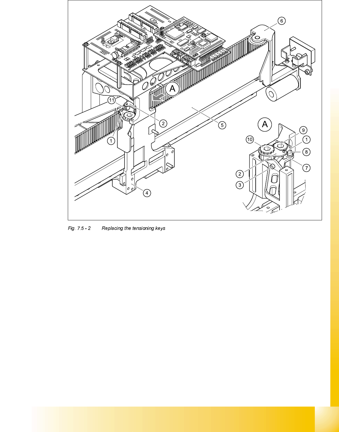
5HSODFLQJWKHWHQVLRQLQJNH\V
7RROVDQGHTXLSPHQW
– Set of DIN 911 Allen keys
– TSM belt tension measuring device, from item number 00326015-01
– "Measuring belt tensions" operating instructions
Parts
'HVLJQDWLRQ )URPLWHPQXPEHU ,WHPLQ)LJ
Tensioning key 00329478-01 (1)
Tensioning key 00329485-01 (2)
5HPRYLQJWKHWHQVLRQLQJNH\V
➠ Switch the placement system off and secure it to prevent switching on again .
➠ Push the head mount towards the deflection pulley (item 6 in Fig. 7.5 - 2).
➠ To slacken the toothed belt (item 5 in Fig. 7.5 - 2)
– loosen the locknut (item 11 in Fig. 7.5 - 2
) and
– turn the hexagon socket-head screw counter-clockwise (item 3 in Fig. 7.5 - 2
).
5HPRYLQJWKHWHQVLRQLQJNH\LWHP V\QFKURQL]LQJGLVNVKRUW
➠ Loosen the M4 x 5 hexagon socket-head screw (item 8 in Fig. 7.5 - 2).
➠ Lift out the tensioning key.
5HPRYLQJWKHWHQVLRQLQJNH\LWHP V\QFKURQL]LQJGLVNORQJ
➠ Unscrew the hexagon socket-head screw (item 3 in Fig. 7.5 - 2) from the spacer bolt (item 7 in
Fig. 7.5 - 2
).
➠ Lift out the tensioning key.
Student Guide HS-50 Advanced II 07/2002 Edition
7 X-Axis
19
(1) Tensioning key
(2) Tensioning key
(3) M4 x 35 hexagon socket-head screw for tensioning the toothed belt
(4) Head mount
(5) Toothed belt for the X-axis
(6) Deflection pulley
(7) Spacer bolt with Benzing U-clip
(8) M4 x 5 hexagon socket-head screw
(9) Synchronizing disk, short
(10) Synchronizing disk, long
(11) Locknut

07/2002 Edition Student Guide HS-50 Advanced II
7 X-Axis
20
,QVWDOOLQJWKHWHQVLRQLQJNH\V
,QVWDOOLQJWKHWHQVLRQLQJNH\LWHP V\QFKURQL]LQJGLVNVKRUW
➠ Place the tensioning key on the ’short’ synchronizing disk (item 9 in Fig. 7.5 - 2).
➠ Use the M4 x 5 hexagon socket-head screw (item 8 in Fig. 7.5 - 2) to fix the tensioning key.
,QVWDOOLQJWKHWHQVLRQLQJNH\LWHPV\QFKURQL]LQJGLVNORQJ
➠ Fit the spacer bolt with the Benzing U-clip (item 7 in Fig. 7.5 - 2) on the new tensioning key.
➠ Place the tensioning key on the ’long’ synchronizing disk (item 10 in Fig. 7.5 - 2).
➠ Use the size 8 Allen key to turn the synchronizing disk slightly until the hexagon socket-head
screw (item 3 in Fig. 7.5 - 2
) can be screwed in.
➠ Pre-tension the toothed belt by turning the hexagon socket-head screw clockwise.
6HWWLQJV
➠ Push the head mount towards the X-axis motor as far as the stop on the elastomeric spring.
➠ Turn the hexagon socket-head screw to set the belt tension to 53 Hz + 1/-3 Hz.
CAUTION
Do not overstretch the toothed belt when adjusting the belt tension.
➠ Secure the hexagon socket-head screw (item 3 in Fig. 7.5 - 2) with the locknut (item 11 in Fig.
7.5 - 2
).
5HSODFLQJWKHGHIOHFWLRQXQLW
7RROVDQGHTXLSPHQW
– Set of DIN 911 Allen keys
– TSM belt tension measuring device, from item number 00326015-01
– "Measuring belt tensions" operating instructions
3DUWV
Deflection unit X, from item number 00330938-01