HS50_advance_level 2.pdf - 第187页
Stud ent Gu ide HS-5 0 Adva nced II 07/2 002 Ed ition 7 X- Axis 29 *DQWU\RU ➠ Remove th e blac k cove r strip on the cross -beam abo ve the gantr y conce rned: – Remove th e fan c able fro m the soc ket. The fan i…
07/2002 Edition Student Guide HS-50 Advanced II
7 X-Axis
28
6HWWLQJV
➠ Push the head mount (item 1 in Fig. 7.5 - 6) towards the X-axis motor unit as far as the stop
on the elastomeric spring.
➠ Turn the hexagon socket-head screw (item 5 in Fig. 7.5 - 6) to set the belt tension to 53 Hz +
1/-3 Hz.
CAUTION
Do not overstretch the toothed belt when adjusting the belt tension.
➠ Secure the hexagon socket-head screw (item 5 in Fig. 7.5 - 6) with the locknut.
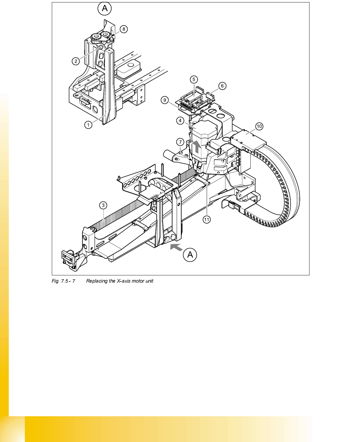
5HSODFLQJWKH;D[LVPRWRUXQLW
7RROVDQGHTXLSPHQW
– Set of DIN 911 Allen keys
– Cable ties
– TSM belt tension measuring device, from item number 00326015-01
– "Measuring belt tensions" operating instructions
3DUWV
X-axis motor unit, from item number 00333167-02
5HPRYLQJWKH;D[LVPRWRUXQLW
➠ Switch the placement system off and secure it to prevent switching on again.
DANGER POWERFUL MAGNETIC FIELD
Always follow the special safety instructions when working in the vicinity of powerful magnetic
fields.

Student Guide HS-50 Advanced II 07/2002 Edition
7 X-Axis
29
*DQWU\RU
➠ Remove the black cover strip on the cross-beam above the gantry concerned:
– Remove the fan cable from the socket. The fan is fixed to the black cover strip.
– Remove the black cover strip (3 M6x8 hexagon socket-head screws).
➠ Cut the cable ties holding the X-axis motor cable.
➠ Remove the cable clamp for the flat ribbon cable (item 11 in Fig. 7.5 - 7)
➠ Unplug all the plugs from the X/Y distributor (item 5 in Fig. 7.5 - 7).
➠ Remove the X/Y distributor (item 5 in Fig. 7.5 - 7).
➠ Remove the board holder for the X/Y distributor (item 9 in Fig. 7.5 - 7).
➠ Remove the cable holder (item 10 in Fig. 7.5 - 7) for the trailing cable.
➠ To slacken the toothed belt (item 3 in Fig. 7.5 - 7)
– loosen the locknut (item 8 in Fig. 7.5 - 7
) and
– turn the hexagon socket-head screw counter-clockwise (item 2 in Fig. 7.5 - 7
).
➠ Loosen the two M6x14 socket head screws (item 7 in Fig. 7.5 - 7) for clamping the X-axis motor
unit (item 4 in Fig. 7.5 - 7
).
➠ Pull the X-axis motor unit (item 4 in Fig. 7.5 - 7) up and out, at the same time pushing the board
holder slightly to the side.
*DQWU\RU
➠ Remove the black cover strip on the cross-beam above the gantry concerned:
– Remove the fan cable from the socket. The fan is fixed to the black cover strip.
– Remove the black cover strip (3 M6x8 hexagon socket-head screws).
➠ Cut the cable ties holding the X-axis motor cable.
➠ Remove the cable clamp for the flat ribbon cable (item 11 in Fig. 7.5 - 7)
➠ Unplug the X-motor plug from the X/Y distributor (item 5 in Fig. 7.5 - 7).
➠ Remove the board holder for the X/Y distributor (item 9 in Fig. 7.5 - 7).
➠ Remove the cable holder (item 10 in Fig. 7.5 - 7) for the trailing cable.
➠ To slacken the toothed belt (item 3 in Fig. 7.5 - 7)
– loosen the locknut (item 8 in Fig. 7.5 - 7
) and
– turn the hexagon socket-head screw counter-clockwise (item 2 in Fig. 7.5 - 7
).
➠ Loosen the two M6x14 socket head screws (item 7 in Fig. 7.5 - 7) for clamping the X-axis motor
unit (item 4 in Fig. 7.5 - 7
).
➠ Pull the X-axis motor unit (item 4 in Fig. 7.5 - 7) up and out, at the same time pushing the board
holder slightly to the side.
07/2002 Edition Student Guide HS-50 Advanced II
7 X-Axis
30
(1) Head mount
(2) M4 x 35 hexagon socket-head screw for tensioning the X-axis toothed belt
(3) Synchroflex X-axis toothed belt
(4) X-axis motor unit
(5) X/Y distributor
(6) X5 socket for X-axis motor
(7) 2 x M6 x 14 hexagon socket-head screws
(8) Locknut
(9) Board holder
(10) Cable holder
(11) Cable clamp