HS50_advance_level 2.pdf - 第191页
Stud ent Gu ide HS-5 0 Adva nced II 07/2 002 Ed ition 7 X- Axis 33 5HS ODFLQJ WKH;D[LV VFDOH 7 RROVDQGHTXLS PHQW – Set of DIN 9 1 1 All en keys – S pacer gauge – SITES T program …

07/2002 Edition Student Guide HS-50 Advanced II
7 X-Axis
32
CAUTION
Make sure that the cables are firmly seated. Otherwise, the high acceleration forces may
cause the cable to slip out of position and shear through.
➠ Turn the hexagon socket-head screw (item 2 in Fig. 7.5 - 7) to pre-tension the X-axis toothed
belt.
➠ Use the three M6 x 8 hexagon socket-head screws to fit the black cover strip to the cross-beam
above the gantry concerned.
➠ Connect the cable of the fan motor to the socket.
6HWWLQJV
➠ Push the head mount (item 1 in Fig. 7.5 - 7) towards X-axis motor unit as far as the stop on the
elastomeric spring.
➠ Turn the hexagon socket-head screw (item 2 in Fig. 7.5 - 7) to set the belt tension to 53 Hz +
1/-3 Hz.
CAUTION
Do not overstretch the toothed belt when adjusting the belt tension.
➠ Secure the hexagon socket-head screw (item 2 in Fig. 7.5 - 7) with the locknut (item 8 in Fig.
7.5 - 7
).
Student Guide HS-50 Advanced II 07/2002 Edition
7 X-Axis
33
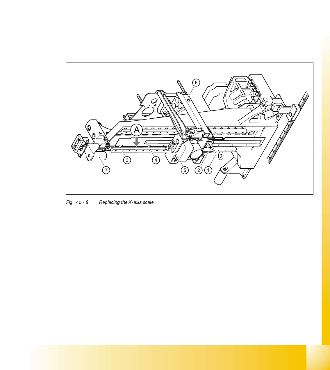
5HSODFLQJWKH;D[LVVFDOH
7RROVDQGHTXLSPHQW
– Set of DIN 911 Allen keys
– Spacer gauge
– SITEST program
3DUWV
X-axis scale for the HS-50, from item number 00329316-01
5HPRYLQJWKH;D[LVVFDOH
(1) Incremental encoder, X-axis
(2) 2 x M3 x 8 hexagon socket-head screws
(3) 11 x M2.5 x 5 hexagon socket-head screws with washers
(4) Scale, X-axis
(5) Proximity switch B1 and B2 for the X-axis
(6) Head mount
(7) Elastomeric spring
A Stop for the scale on the bars
➠ Switch the placement system off and secure it to prevent switching on again.

07/2002 Edition Student Guide HS-50 Advanced II
7 X-Axis
34
DANGER POWERFUL MAGNETIC FIELD
Always follow the special safety instructions when working in the vicinity of powerful magnetic
fields.
➠ Loosen two M3 x 8 hexagon socket-head screws (item 2 in Fig. 7.5 - 8) to remove the incre-
mental encoder for the X-axis (item 1 in Fig. 7.5 - 8
).
➠ Loosen the eleven M2.5 x 5 hexagon socket-head screws (item 3 in Fig. 7.5 - 8) with washers.
➠ Move the head mount (item 6 in Fig. 7.5 - 8) across as far as the elastomeric spring (item 7 in
Fig. 7.5 - 8
) in order to prevent any damage to proximity switches B1 and B2 (item 5 in Fig. 7.5
- 8).
➠ Remove the scale (item 4 in Fig. 7.5 - 8).
,QVWDOOLQJWKH;D[LVVFDOH
➠ Carefully insert the scale.
CAUTION
Do not touch the incremental tracks with bare fingers.
➠ Loosely tighten the eleven M2.5 x 5 hexagon socket-head screws with washer.
➠ Push the scale along the bars as far as the stop (item A in Fig. 7.5 - 8)
➠ Tighten the M2.5 x 5 hexagon socket-head screws.
➠ Use the feeler gauge to set the 0.4 mm gap between the incremental encoder and scale.
➠ Use the two M3x8 hexagon socket-head screws (item 2 in Fig. 7.5 - 8) to fix the incremental
encoder (item 1 in Fig. 7.5 - 8
) to the X-axis.
6HWWLQJV
➠ Set and calibrate the collect&place head and gantry axes using the SITEST program.