HS50_advance_level 2.pdf - 第206页
07/2002 Editio n Student G uide HS -50 Advanc ed II 7 X-Axis 48 $ QDORJH=H UR3XOVHRIW KH*DQWU \ $ [HV NOTE The puls e width of t he anal og zero pulse is depen dent on the sp eed at w hich t he axis is tr ave…
Student Guide HS-50 Advanced II 07/2002 Edition
7 X-Axis
47
3URFHGXUH
➠ Turn on the machine.
➠ Relate your measurement setup to the x-, or y- axis respectively. (See ).
➠ Adjust the oscilloscope.
➠ Set the track signal tester to the "Oscilloscope cal" position.
➠ With the help of the positioning switches CH1 and CH2, move the light spot exactly to the
center of the crosshairs of the screen.
➠ Set the track signal tester to the "signal output" position.
➠ Manually, move the appropriate axis (x = head / y = gantry) back and forth.
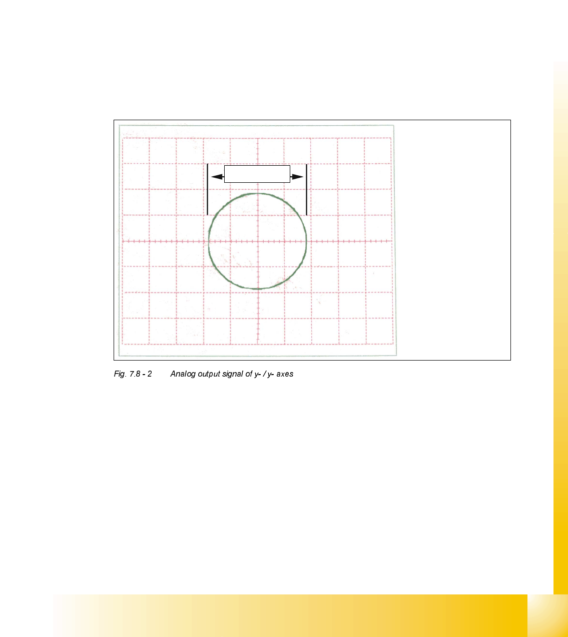
– If you adjusted the read head correctly, the following illustration will appear on the screen of
the oscilloscope:
Spur A / track
A
Spur B / track
B
1,8- 2,0 V

07/2002 Edition Student Guide HS-50 Advanced II
7 X-Axis
48
$QDORJH=HUR3XOVHRIWKH*DQWU\$[HV
NOTE
The pulse width of the analog zero pulse is dependent on the speed at which the axis is
traversed.
0HDVXULQJ6HTXHQFH
➠ Turn the main switch to "ON".
➠ Connect the track signal tester to the incremental encoder 1 of the x- / y- axis.
(See
).
NOTE
The testing sequences of the x- and y- axes are identical.
2VFLOORVFRSH6HWWLQJV
➠ Connect the oscilloscope to the track signal tester.
➠ Set the oscilloscope to the values of the table below.
&DOLEUDWLRQRI2VFLOORVFRSH
➠ Set the track signal tester to selector switch "Oscilloscope cal.".
➠ With the help of the positioning switch of CH 1, set the direct current signal on the center of the
upper half of the screen.
0HDVXULQJWKH=HUR3XOVH
➠ Set the oscilloscope to the value of the table below:
&KDQQHO 6LJQDO &RXSOLQJ <'HIHOFWLRQ 7ULJJHU ;'HIOHFWLRQ
CH 1
"Oscilloscope
cal."
zero pulse DC 0.5 V/ DIV auto 20 ms
&KDQQHO 6LJQDO &RXSOLQJ <'HIOHFWLRQ 7ULJJHU ;'HIOHFWLRQ

Student Guide HS-50 Advanced II 07/2002 Edition
7 X-Axis
49
➠ Set the track signal tester to position "Signal output".
➠ Manually, move the appropriate axis (x = head / y = gantry) back and forth.
CH 1
signal output zero pulse DC 0.5 V/ DIV
2.5V norm
pre- trig. 50%
20 ms