HS50_advance_level 2.pdf - 第212页
07/2002 Editio n Student G uide HS -50 Advanc ed II 7 X-Axis 54 .(< TBS 200 / 10 X = S ervo bo ard x-axi s TBS 200 / 15 Y = S ervo bo ard y-axi s (1) LED: Rea dy for oper ation (2) LED: S ervo ena ble (3) LED:…
Student Guide HS-50 Advanced II 07/2002 Edition
7 X-Axis
53
$[LVG\QDPLFV
NOTE:
All SITEST functions are explained by the use of gantry 1
(TXLSPHQWDQG7HVW'HYLFHV
– 2 or 4 channel storage oscilloscope.
– SIPLACE axis test box, complete.
–SITEST software.
NOTE
The machine must have reached its operating temperature before you begin to adjust the axes.
Therefore, make sure to switch it on, at least 30 minutes before you begin to work.
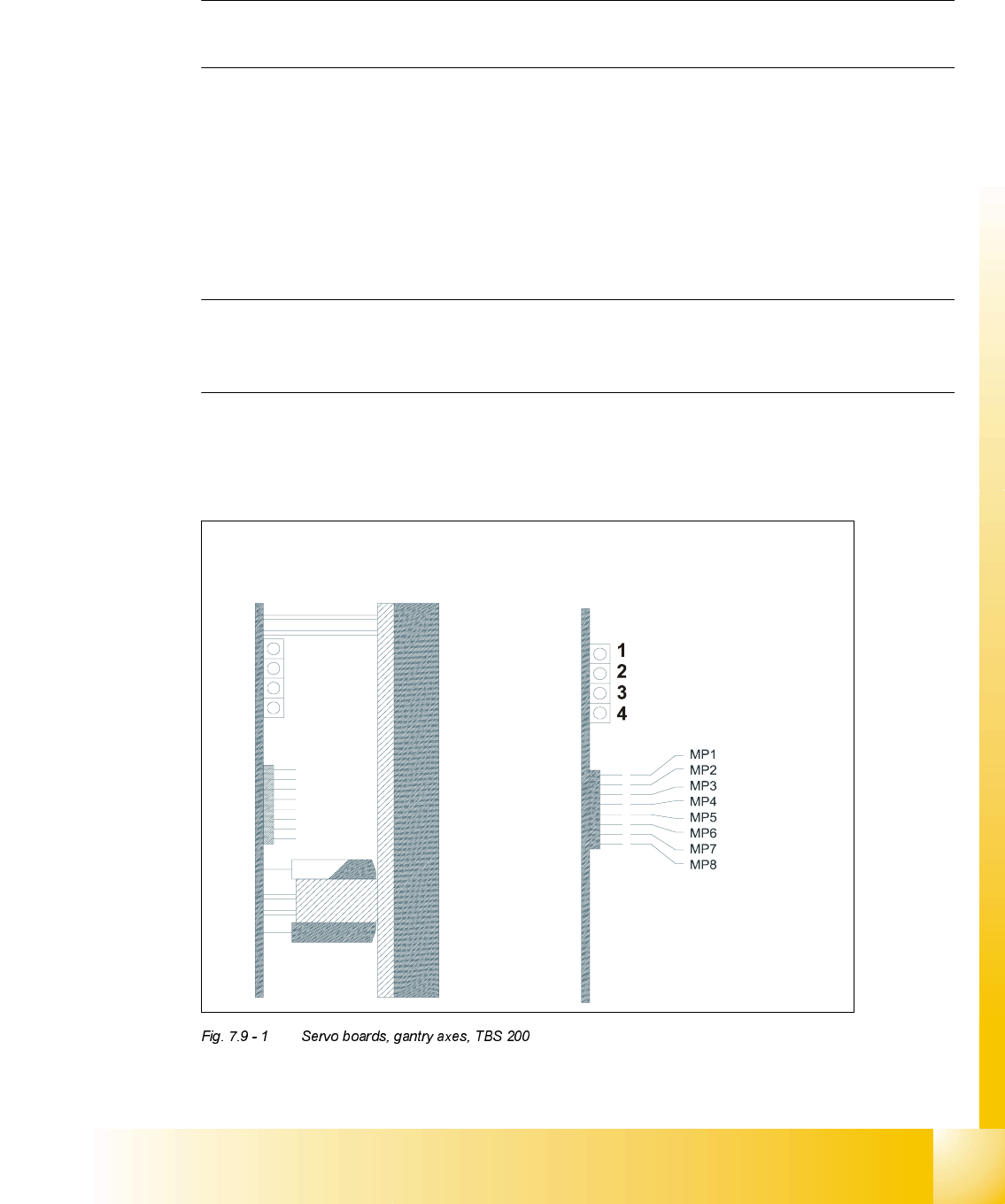
6HUYR%RDUGV*DQWU\$[HV+6
T
BS 200 / 10X
T
BS 200 / 15Y

07/2002 Edition Student Guide HS-50 Advanced II
7 X-Axis
54
.(<
TBS 200 / 10X = Servo board x-axis
TBS 200 / 15Y = Servo board y-axis
(1) LED: Ready for operation
(2) LED: Servo enable
(3) LED: I
RMS
limit
(4) LED: Error
MP1 = Nominal current "I-S (U)"
MP2 = Nominal current "I-S (W)"
MP3 = Actual current "I-ist (U)"
MP4 = Actual current "I-ist (W)"
MP5 = "U-nominal (U)"
MP6 = "U-nominal (W)"
MP7 = Free
MP8 = Reference potential "0V"
NOTE
For a proper triggering connect the endsignal and the nominal current.
Student Guide HS-50 Advanced II 07/2002 Edition
7 X-Axis
55
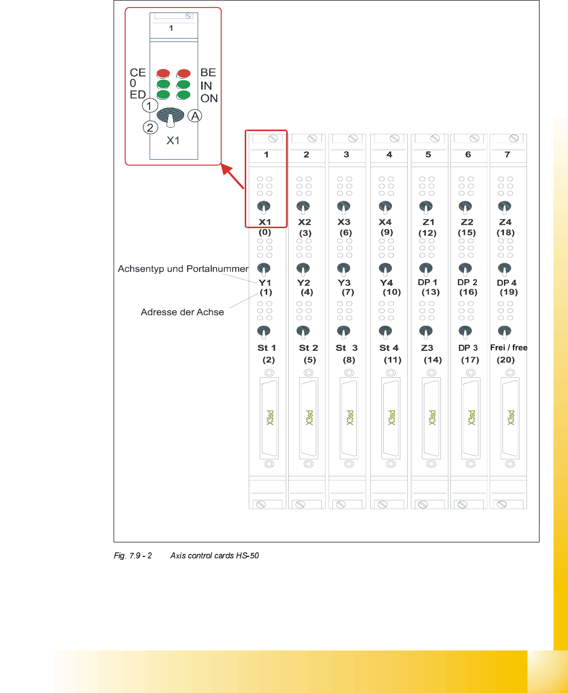
2YHUYLHZRI$[HV&RQWURO&DUGV+6
type of axis and gantry number
adress of axis
CE = Counting error
0 = Zero pulse
ED = End signal
BE = General error, module error
IN = Initialized
ON = Servo ON
(A) "Axis enable" switch
(1) Servo ON