HS50_advance_level 2.pdf - 第237页
Stud ent Gu ide HS-5 0 Adva nced II 07/2 002 Ed ition 8 Y- Axis 19 1A, 1B, 1C , 1D P ermanen t magne ts for the Y - axis lin ear drive for gantr ies 1 and 4 2A, 2B, 2C , 2D P ermanen t magne ts for the Y - axis lin ear…
07/2002 Edition Student Guide HS-50 Advanced II
8 Y-Axis
18
5HSODFLQJWKHOLQHDUPRWRUSULPDU\SDUW
7RROVDQGHTXLSPHQW
– Set of DIN 911 Allen keys
– Cable ties
– TSM belt tension measuring device, from item number 00326015-01
– "Measuring belt tensions" operating instructions
3DUWV
Linear motor - primary part, from item number 00333148-01
5HPRYLQJWKHSHUPDQHQWPDJQHWV
➠ Switch the placement system off and secure it to prevent switching on again.
DANGER POWERFUL MAGNETIC FIELD
Always follow the special safety instructions when working in the vicinity of powerful magnetic
fields (see section 8.4.2, page 8 - 16 onward).
➠ Move the gantry in the PCB transport direction and position it so that the permanent magnets
can be removed:
– For gantry 1, position above the permanent magnets, item 1C in Fig. 8.5 - 1
– For gantry 2, position above the permanent magnets, item 2C in Fig. 8.5 - 1
– For gantry 3, position above the permanent magnets, item 2C in Fig. 8.5 - 1
– For gantry 4, position above the permanent magnets, item 1C in Fig. 8.5 - 1
➠ Remove the black cover strips on the cross-beam above the gantry concerned (3 M6 x 8 hexa-
gon socket-head screws)
Student Guide HS-50 Advanced II 07/2002 Edition
8 Y-Axis
19
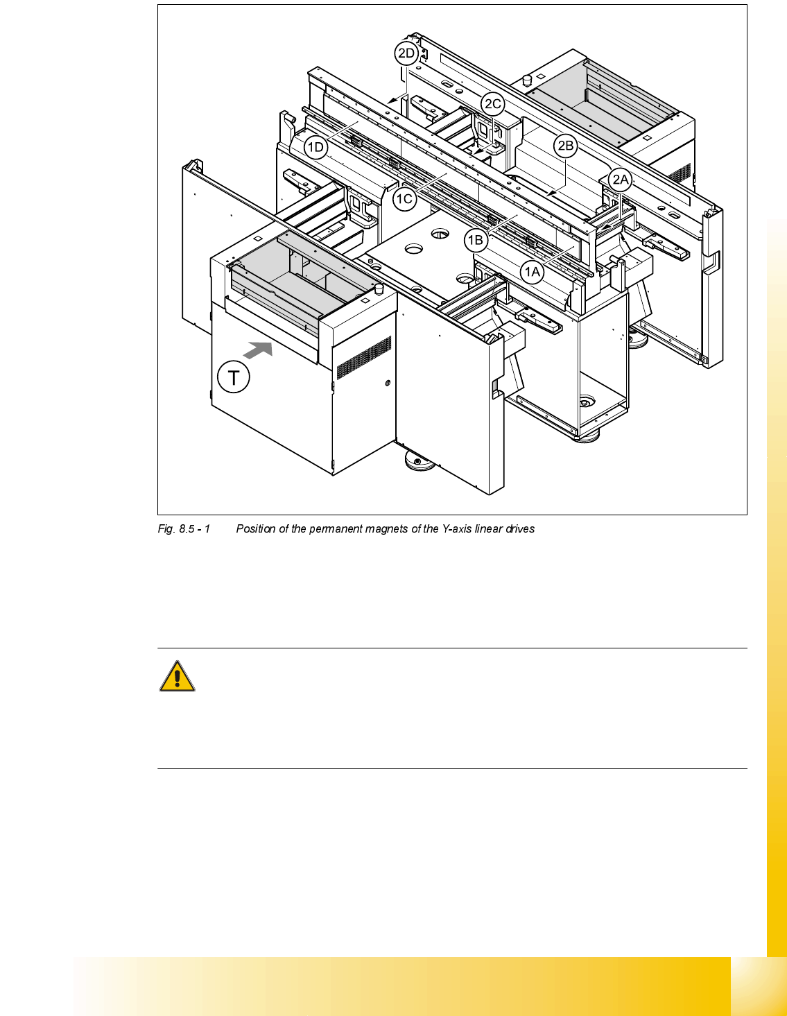
1A, 1B, 1C, 1D Permanent magnets for the Y-axis linear drive for gantries 1 and 4
2A, 2B, 2C, 2D Permanent magnets for the Y-axis linear drive for gantries 2 and 3
T Transport direction
CAUTION
When permanent magnets are placed on a magnetic surface (e.g. iron, nickel or steel), be ex-
tremely careful not to catch your hands or fingers between the surface and the permanent magnet.
If you do, you will not be able to lift the magnet from the surface on your own.

07/2002 Edition Student Guide HS-50 Advanced II
8 Y-Axis
20
➠ Remove the permanent magnets from the gantry concerned:
*DQWU\RU
➠ Loosen the four M6 x 12 hexagon socket-head screws on the permanent magnet (see item 1A
or 2A in Fig. 8.5 - 1
).
➠ Lift the permanent magnet and place it on a clean, non-magnetic surface (such as a plank of
wood).
➠ Loosen the 16 M6 x 12 hexagon socket-head screws on the permanent magnet (item 1B or 2B
in Fig. 8.5 - 1
).
➠ Set down the permanent magnet.
*DQWU\RU
➠ Loosen the 16 M6 x 12 hexagon socket-head screws on the permanent magnets (see item 2C
and 2D or 1C and 1D in Fig. 8.5 - 1
).
➠ Lift the permanent magnet and place it on a clean, non-magnetic surface (such as a plank of
wood).