HS50_advance_level 2.pdf - 第240页
07/2002 Editio n Student G uide HS -50 Advanc ed II 8 Y-Axis 22 ➠ Loose n the nine M5 x 20 hex agon so cket-he ad screws (item 3 in Fig. 8.5 - 3 ) and rem ove the primar y part later ally (ite m 2 in Fig. 8.5 - 3 ). ➠ Ma…
Student Guide HS-50 Advanced II 07/2002 Edition
8 Y-Axis
21
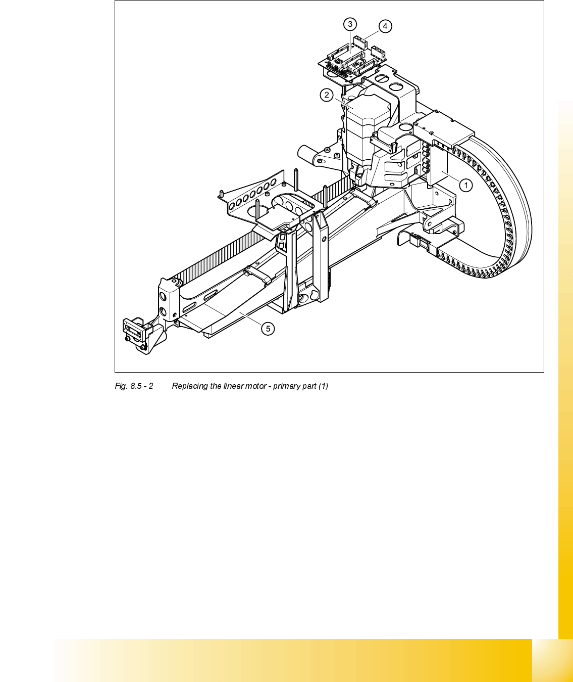
5HPRYLQJWKHSULPDU\SDUWRIWKHOLQHDUPRWRU
➠ Remove the X-axis motor unit.
(1) Linear motor - primary part
(2) X-axis motor unit
(3) X/Y distributor
(4) Socket X4 for the connecting cable of the primary part
(5) Gantry
07/2002 Edition Student Guide HS-50 Advanced II
8 Y-Axis
22
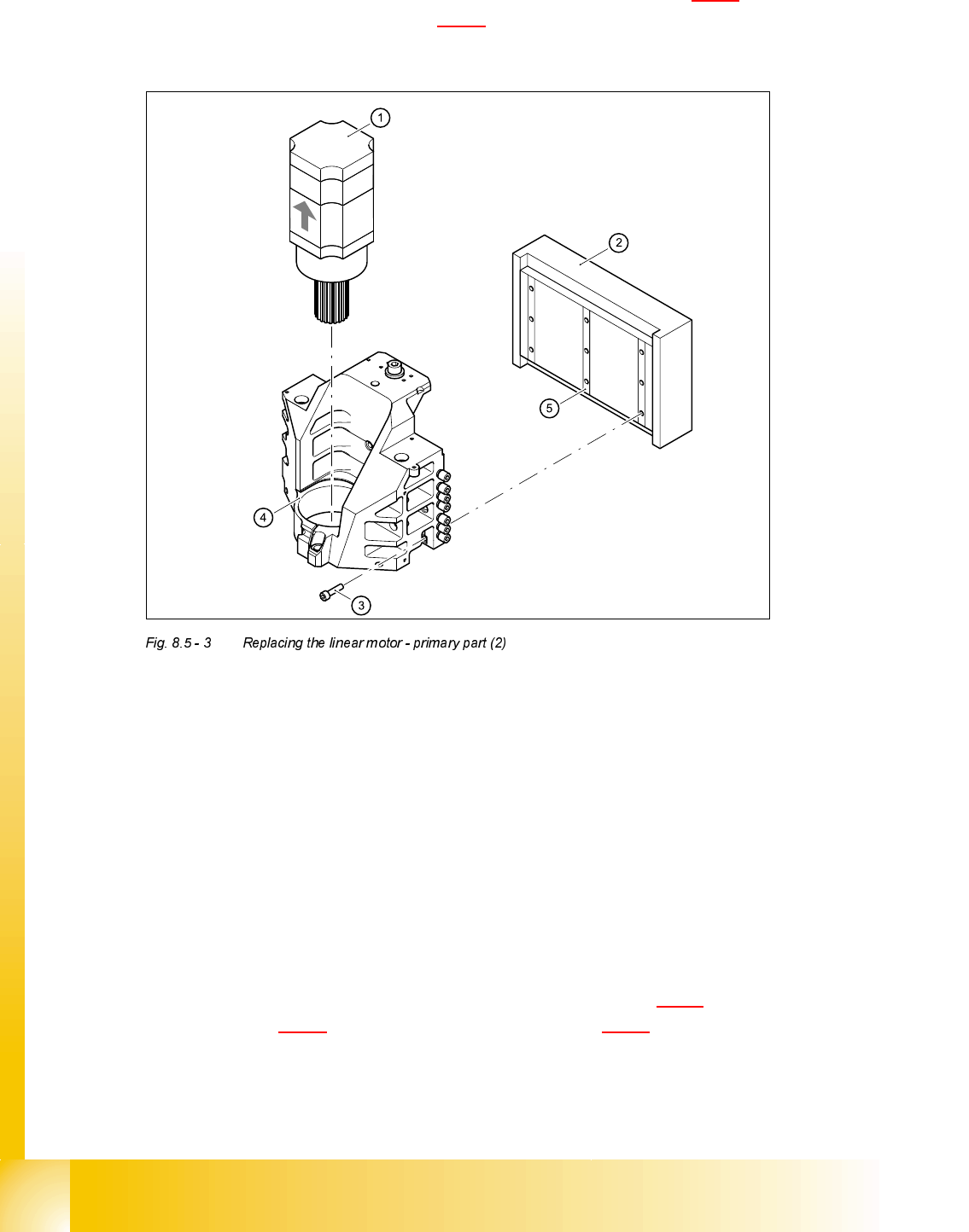
➠ Loosen the nine M5 x 20 hexagon socket-head screws (item 3 in Fig. 8.5 - 3) and remove the
primary part laterally (item 2 in Fig. 8.5 - 3
).
➠ Make sure that the lock rails will not drop.
(1) X-axis motor unit
(2) Linear motor - primary part
(3) 9 x M5 x 20 hexagon socket-head screws
(4) Motor bracket with press-fit connection (pneumatic system)
(5) Lockrail
,QVWDOOLQJWKHSULPDU\SDUWRIWKHOLQHDUPRWRU
➠ Fit scotch tape on the lower edge of the primary part of the linear motor to prevent the lockrails
from dropping.
➠ Push in the primary part from the side.
➠ Use the nine M5 x 20 hexagon socket-head screws (item 3 in Fig. 8.5 - 3) to fix the primary part
(item 2 in Fig. 8.5 - 3
) to the motor bracket (item 4 in Fig. 8.5 - 3).
Make sure that the primary part is aligned in parallel to the permanent magnet.
➠ Fit the X-axis motor unit.
➠ Fix all the cables with cable ties.
Student Guide HS-50 Advanced II 07/2002 Edition
8 Y-Axis
23
CAUTION Make sure that the cables are firmly seated. Otherwise, the high acceleration
forces may cause the cable to slip out of position and shear through.
➠ Fit the permanent magnets (4 or 16 M6 x 12 hexagon socket-head screws).
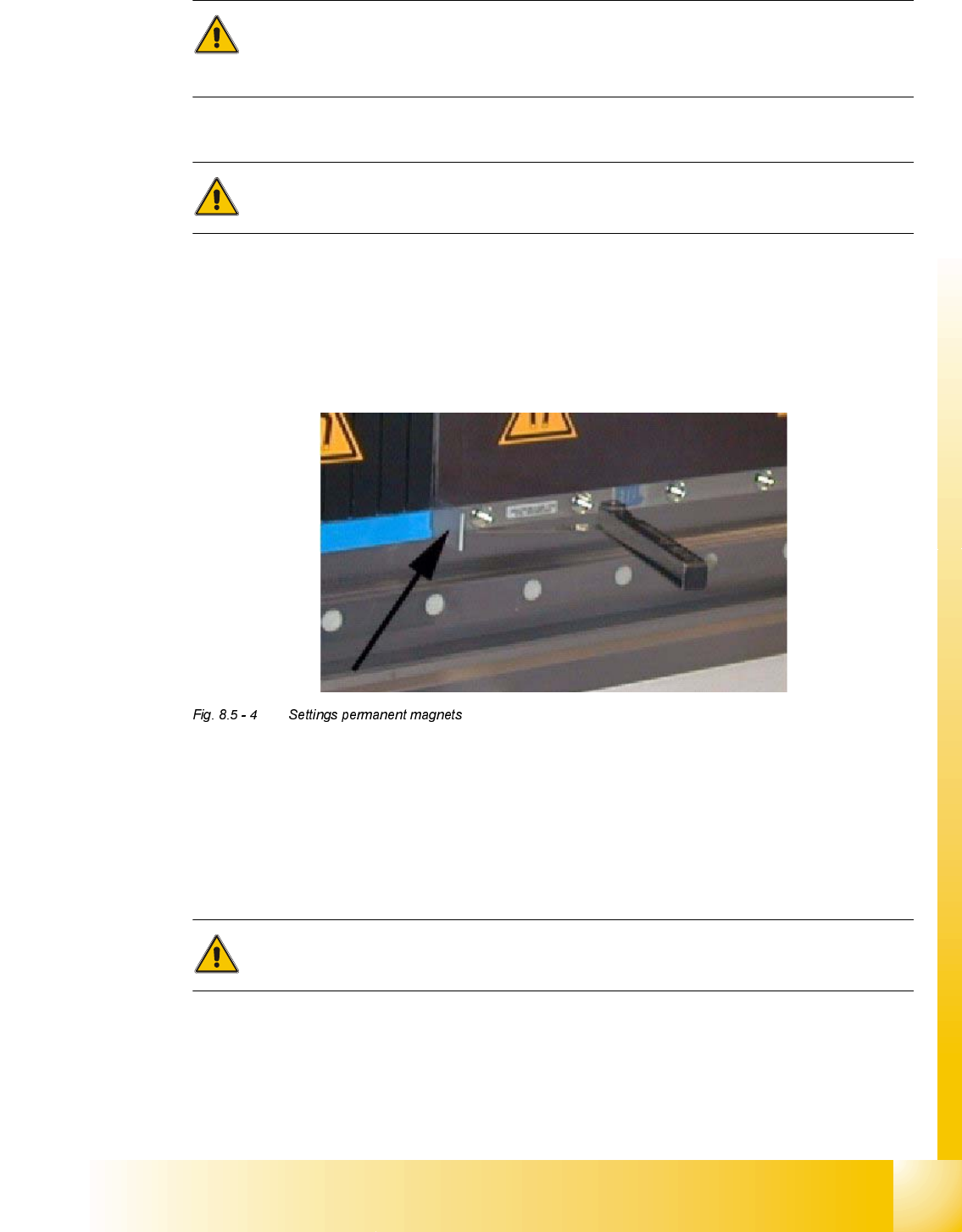
CAUTION Settings for the permanent magnetsn (see Fig. 8.5 - 4 ).
➠ Place two 1 mm thick feeler gauges beneath the magnetic plate so that the holes line up ex-
actly with the screw.
➠ Before you attach the magnetic plate, place a 0.8 mm thick non-magnetic spacer (e.g. incre-
mental encoder film) between the magnetic plates, otherwise they will be attracted to one an-
other and will be difficult to separate.
➠ Fit the black cover strips on the cross-beam above the gantry concerned (3 M6 x 8 hexagon
socket-head screws).
6HWWLQJV
➠ Use the belt tension measuring device to set the X-axis toothed belt tension to 53 Hz + 1/-3 Hz.
CAUTION Do not overstretch the toothed belt when adjusting the belt tension.
➠ Secure the hexagon socket-head screw.