HS50_advance_level 2.pdf - 第275页
Stud ent Gu ide HS-5 0 Adva nced II 07/2 002 Ed ition 9 Z-Axis 15 .H\ (1) M2 x 4 hexagon s ocket- head screw (2) S t op pi ece (3) 2 x M 2.5 x 8 h exagon s ocket-h ead scr ew (4) S top (5) Snap jaws o f the z ax is (6)…
07/2002 Edition Student Guide HS-50 Advanced II
9 Z-Axis
14
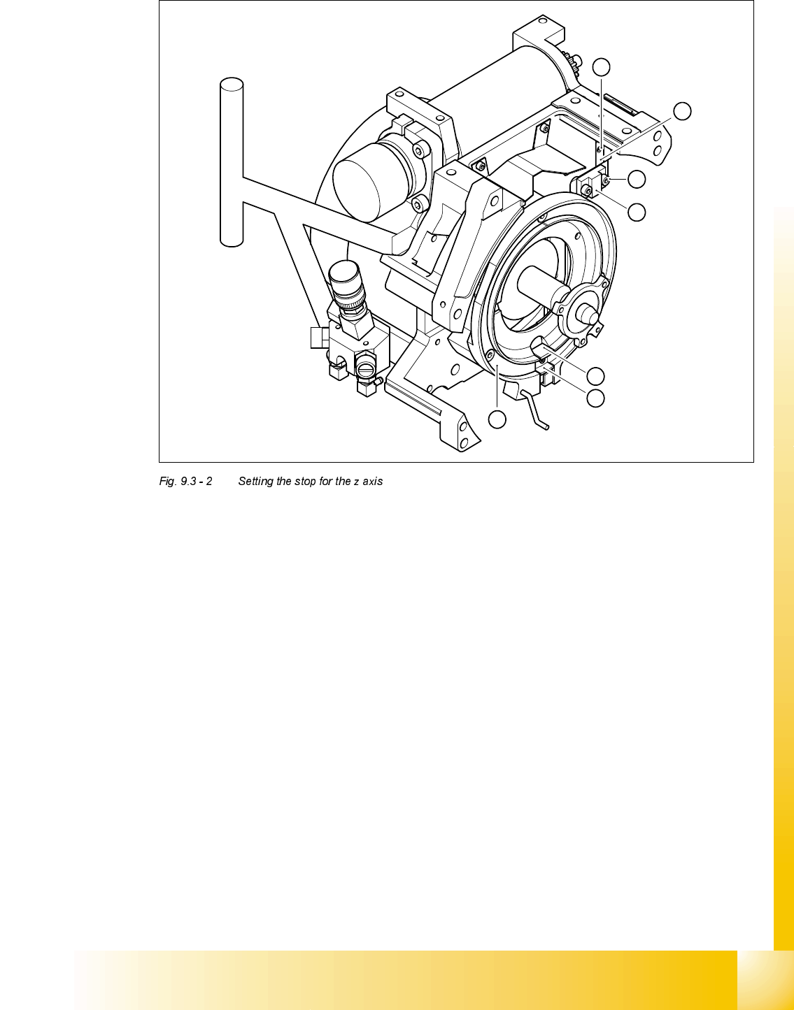
6HWWLQJWKHVWRSIRUWKH=D[LV
7RROVDQGHTXLSPHQW
– Set of DIN 911 Allen keys
– Gauge for z axis, from item no. 00331308-01
6HWWLQJV
➠ Dismantle the front part of the revolver head as described in section 10.7.2, page 10 - 29 in the
Service manual.
➠ Dismantle the star as described in the Service manual.
NOTE
The Z-axis must be correctly mounted
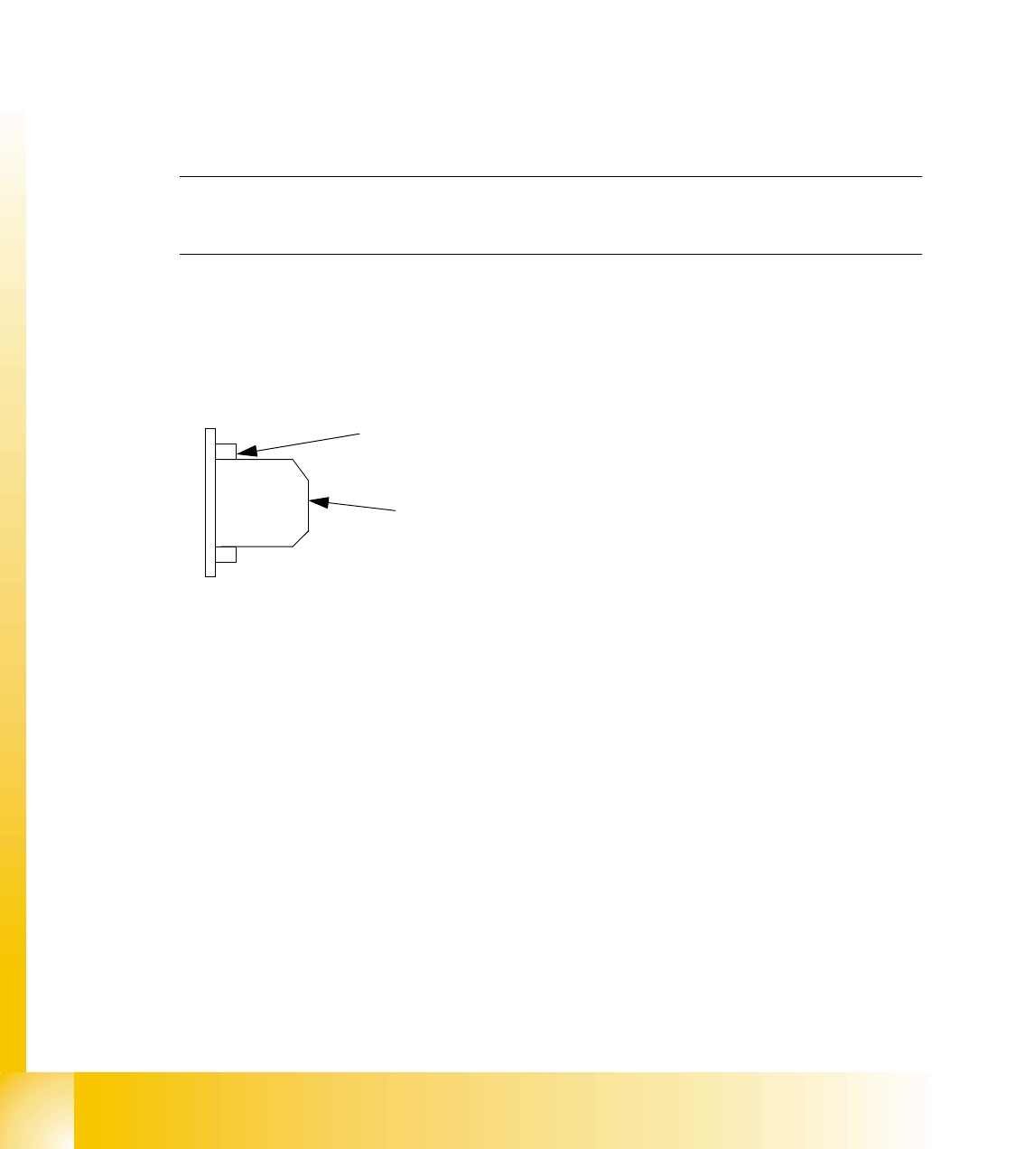
➠ Screw the stop piece with both hexagon socket screws M2.5x8 (position 3 in figure 8.3.2)
tightly to the drive belt, so that the clamping device is firmly fixed between the teeth of the drive
belt. (see fig.)
➠ Carefully raise the Z-axis by hand, until the snap jaws (Pos. 5) are at least above the raceway
(Pos. 6).
➠ Put the raceway with the Z-axis gauge into the position marked A.
➠ Unscrew the hexagon socket screw of the stop piece. (Pos. 1 in fig. 8.3.2)
➠ Insert the stop piece in to the stopping face until contact is made.(Pos. 2 in fig. 8.3.2)
➠ Fix the stop piece to the hexagon socket screw M2x4.
Do not use a ball-end-allen wrench.
drivebelt tooth
Clamping device between the
teeth of the drive belt
Student Guide HS-50 Advanced II 07/2002 Edition
9 Z-Axis
15
.H\
(1) M2x4 hexagon socket-head screw
(2) Stop piece
(3) 2 x M2.5x8 hexagon socket-head screw
(4) Stop
(5) Snap jaws of the z axis
(6) Raceway
(A) Insert the z axis gauge here
6
A
5
4
3
2
1
07/2002 Edition Student Guide HS-50 Advanced II
9 Z-Axis
16
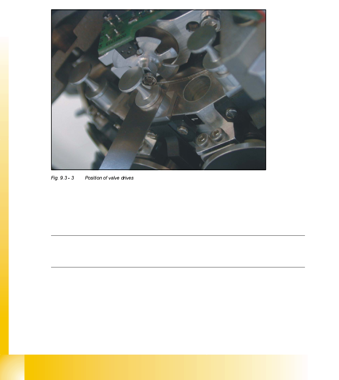
$GMXVWPHQWRI0HFKDQLFDO3RVLWLRQRI9DOYH'ULYHV
➠
Set the motor position of the valve drives "Pick-up / Placement" and "Ejection" according to the
figure below.
➠ Insert the distance gauge between valve plunger and valve casing.
➠ Turn the valve drive to 90° degrees, opposite to its initial position.
2WKHU0HFKDQLFDO$GMXVWPHQWVRQWKH6WDU
➠
Insert the blast air transition tubes so that they will protrude 0.5 mm from the surface of the
circular arc guide.
NOTE
The blast air tubes at the valve plungers should be at a distance of 0.2 mm from the encoder
of the dp - axis.