HS50_advance_level 2.pdf - 第277页
Stud ent Gu ide HS-5 0 Adva nced II 07/2 002 Ed ition 9 Z-Axis 17 =D[LVFR QWURORYHUYLHZ Her e we ca n see th at th e bas ic el ement s of the Z a xis co ntr ol syst em ar e the s ame as the ot her axis we have s t…
07/2002 Edition Student Guide HS-50 Advanced II
9 Z-Axis
16
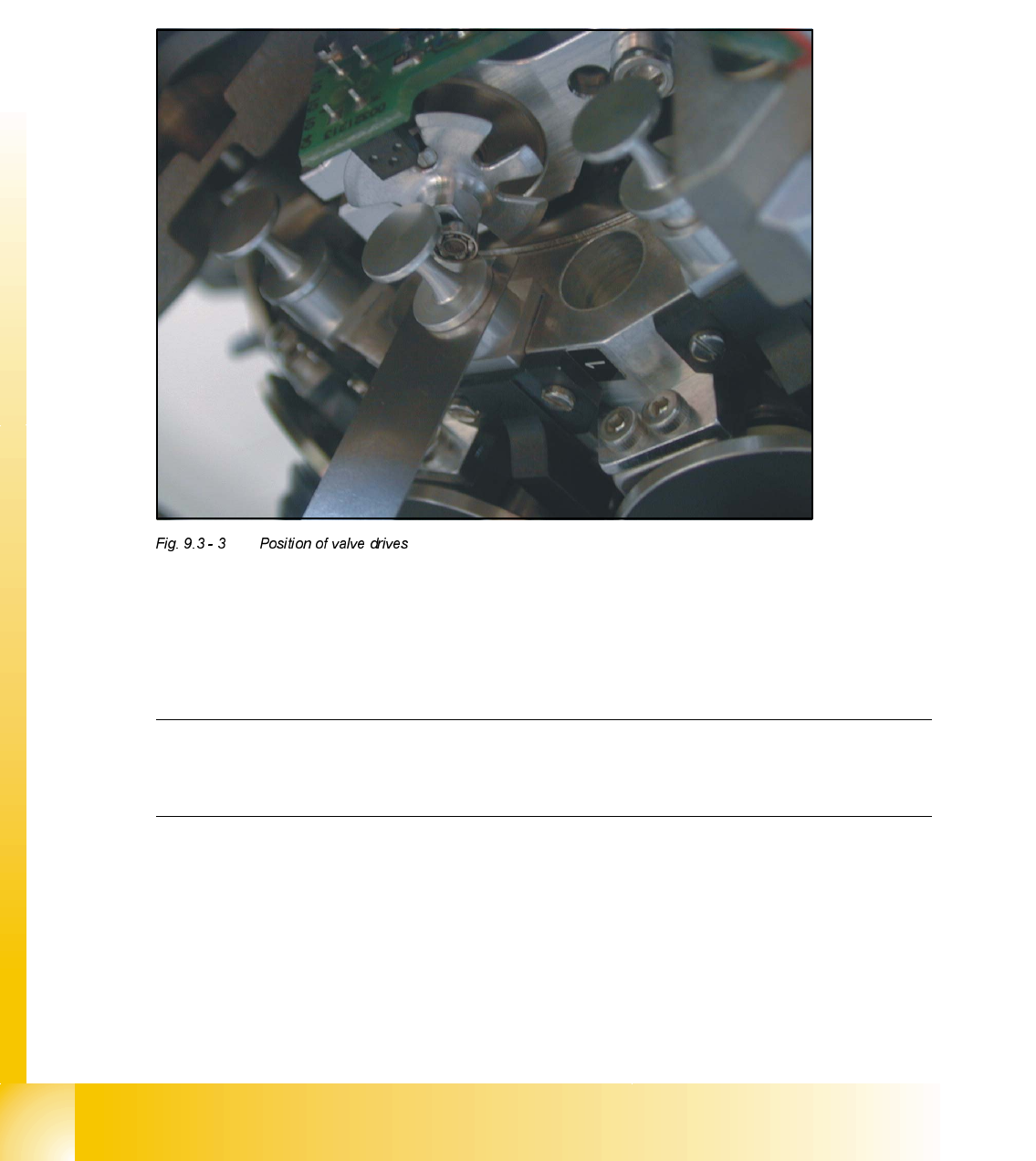
$GMXVWPHQWRI0HFKDQLFDO3RVLWLRQRI9DOYH'ULYHV
➠
Set the motor position of the valve drives "Pick-up / Placement" and "Ejection" according to the
figure below.
➠ Insert the distance gauge between valve plunger and valve casing.
➠ Turn the valve drive to 90° degrees, opposite to its initial position.
2WKHU0HFKDQLFDO$GMXVWPHQWVRQWKH6WDU
➠
Insert the blast air transition tubes so that they will protrude 0.5 mm from the surface of the
circular arc guide.
NOTE
The blast air tubes at the valve plungers should be at a distance of 0.2 mm from the encoder
of the dp - axis.
Student Guide HS-50 Advanced II 07/2002 Edition
9 Z-Axis
17
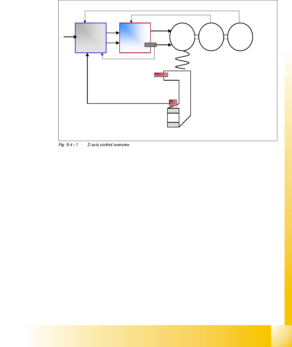
=D[LVFRQWURORYHUYLHZ
Here we can see that the basic elements of the Z axis control system are the same as the other
axis we have studied. The DC control system consisting of an Axis Controller, Servo Amplifier, Mo-
tor and track signals remains the same.
The primary difference if the way the Z axis ’End Signal’ is generated. On the diagram we can
clearly see that the Z axis ’Light barrier bottom’ is used to generate this signal in most cases. Only
when larger placement forces are required is the other control method used where the ’End Signal’
is generated by the ’Current Sensor’ on the Servo card. More details on the subject are given later
in the section ’Z axis Modes’.
The remaining element shown in the diagram is the ’Light barrier up’ this is used to control various
items and more detail is given on the timing diagrams shown in the following section.
To get the end signal very
quickly we use the light
barrier bottom signal.
Axis
controller
Servo
amplifier
M
=
G
=
Rotor
position
encoder
Light barrier up
End signal with
Light barrier
bottom
End signal from
current sensor
We define higher placement
forces with end signal triggered
by current sensor signal.

07/2002 Edition Student Guide HS-50 Advanced II
9 Z-Axis
18
6LJQDO7LPLQJ&KDUWRQWKH&ROOHFW3ODFH+HDG3LFN8S&\FOH
a The end signal of the star axis starts the swivel - in function at the dp-station.
s The last end signal from the X- Y- or star axis and the OK-message "feeder ready" starts the
movement downward of the Z-axis.
d The end signal of the swivel in - function starts the dp-axis for an empty segment and prepares
the pick - up angle for this segment.
f The end signal of the dp-axis starts the swivel - out function.
g The end signal of the Z-axis on the bottom (light barrier) starts the stepper motor vacuum- / air
kiss valve (the stepper motor rotates by 180° to connect the vacuum channel to the segment).
h The 90 degree movement signal of the stepper motor starts the Z-axis upwards. The stepper
motor continue moving until reached 180 degree.
j The light barrier Z-axis in upper position disables the light barrier signal on the bottom and
starts the gantry axes. At this point the vacuum check for pick - up of a component is per-
formed.
k The end signal of the Z-axis on top (0-position) starts the star axis.